
A permanent magnet motor for a fixed device

A permanent magnet motor and fixing device technology, which is applied to electromechanical devices, electric components, cooling/ventilating devices, etc., can solve the problems of time-consuming and laborious disassembly, affecting the stability and reliability of the motor, and unstable fixing of the motor, so as to achieve convenient installation. Effect

Active Publication Date: 2019-07-02
黑龙江省碧水清源环保设备有限公司
View PDF11 Cites 0 Cited by
  • Summary
  • Abstract
  • Description
  • Claims
  • Application Information

AI Technical Summary

Problems solved by technology

[0002] Permanent magnet motor is a common power equipment. In order to improve the heat dissipation performance of the motor, the outer shell of the motor is usually an aluminum alloy cylinder. In order to fix the cylinder to the driving device, a special frame needs to be set under the motor. Now Some machine bases are usually fixed in one direction, and the motor is easy to move back and forth in series, which affects the stability and reliability of the motor. For example, the patent No. CN204794467U includes a motor part, and the upper and lower sides of the motor part are respectively equipped with a The detachable fixing clip seat solves the problem of unstable fixing of the motor, but there is still the problem of time-consuming and labor-intensive disassembly

Method used


Image

  • A permanent magnet motor for a fixed device
  • A permanent magnet motor for a fixed device
  • A permanent magnet motor for a fixed device

Examples


Embodiment Construction

[0019] The following will clearly and completely describe the technical solutions in the embodiments of the present invention with reference to the accompanying drawings in the embodiments of the present invention. Obviously, the described embodiments are only some, not all, embodiments of the present invention. Based on the embodiments of the present invention, all other embodiments obtained by persons of ordinary skill in the art without making creative efforts belong to the protection scope of the present invention.

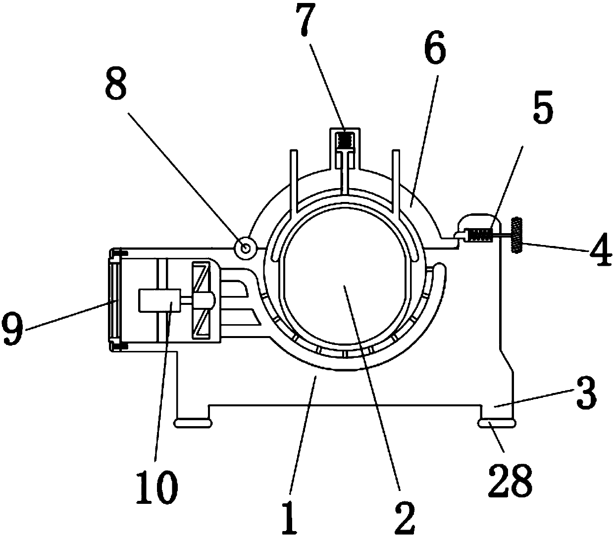
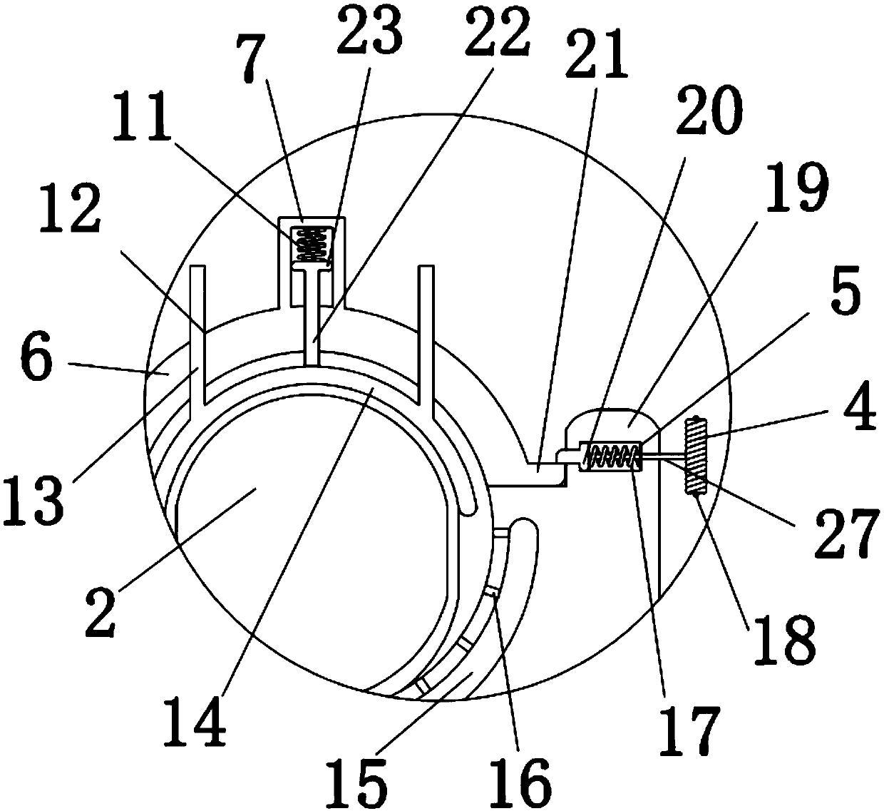
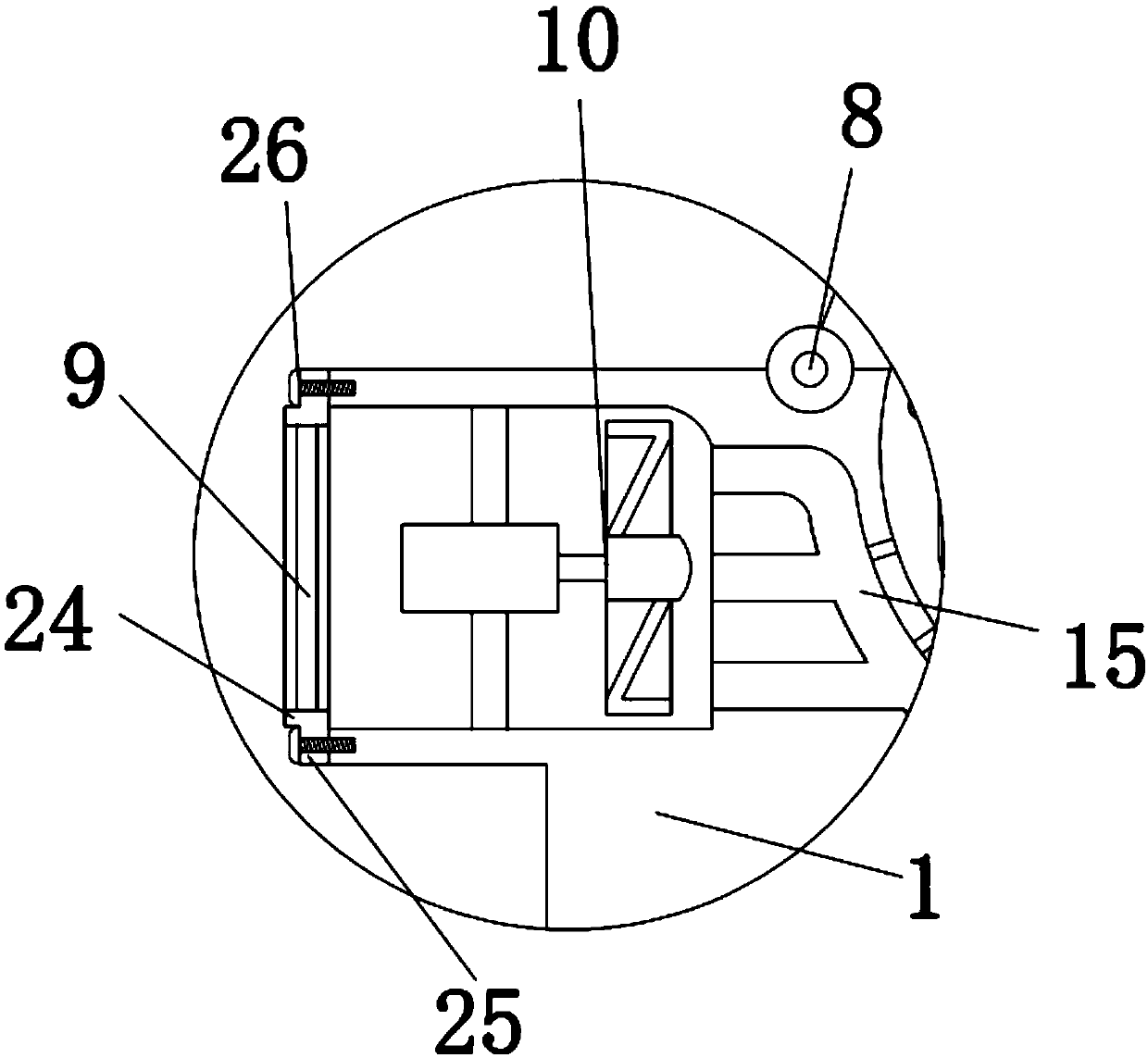
[0020] see Figure 1-3 , the present invention provides a technical solution: a permanent magnet motor of a fixing device, comprising a bracket 1 and a motor 2, the upper surface of the bracket 1 is equipped with a motor 2, and the four corners of the lower surface of the bracket 1 are provided with legs 3, and the legs 3 are used To support the bracket 1, the lower surface of the leg 3 is provided with a rubber pad 28. The rubber pad 28 can protect the leg 3 ...


PUM


Abstract

The invention discloses a water-cooled permanent magnet motor for fixing devices, which includes a bracket and a motor. The motor is mounted on the upper surface of the bracket. A top cover is arranged on the upper end of a hinge. The bracket is connected with the top cover through the hinge. A clamping block is arranged at the left end of a second spring. The clamping block is connected in a matching manner with a cushion block. A pull rod is arranged at the right end of the clamping block. After the external power supply of a fan is switched on, the fan rotates and pushes air to flow into the bracket from outside and move to the right, the flow of air is speeded up, and the air can flow quickly to take away the heat on the surface of the motor to cool the motor. The flowing air is limited through vent holes, in order to prevent the air flow direction from being out of control to decrease the cooling effect. The liquid can adapt to different types of motors. Through matching connection between the clamping block and the cushion block, the clamping block can fix the cushion block, and thus, the top cover can be fixed and prevented from loosening.

Description

technical field [0001] The invention relates to the technical field of permanent magnet rotating machines, in particular to a permanent magnet motor of a fixing device. Background technique [0002] Permanent magnet motor is a common power equipment. In order to improve the heat dissipation performance of the motor, the outer shell of the motor is usually an aluminum alloy cylinder. In order to fix the cylinder to the driving device, a special frame needs to be set under the motor. Now Some machine bases are usually fixed in one direction, and the motor is easy to move back and forth in series, which affects the stability and reliability of the motor. For example, the patent No. CN204794467U includes a motor part, and the upper and lower sides of the motor part are respectively equipped with a Although the detachable fixing clip seat solves the problem of unstable fixing of the motor, it still has the problem of time-consuming and laborious disassembly. Contents of the inv...

Claims


Application Information

Patent Timeline
Patent Type & Authority Patents(China)
IPC IPC(8): H02K5/00H02K9/04
CPCH02K5/00H02K9/04
Inventor 刘和来
Owner 黑龙江省碧水清源环保设备有限公司
Learn More