


Quick Research
Generate reliable direction feasibility study reports for your R&D in just a few steps.

Technical Q&A
Discover and master advanced knowledge NOW. Basics, ideas, possibilities, all at once.

Find Solutions
As an expert in R&D theories, this can generate solutions to your technical problems instantly.

Evaluate Feasibility
Analyze your overall solution with one click, know your potential R&D risks in advance.

Monitor Landscape
Get weekly tech updates, stay abreast of the latest tech innovations and key insights.
Video monitoring equipment used for transformer
A video surveillance and transformer technology, applied in transformer/inductor components, mechanical equipment, transformer/reactor installation/support/suspension, etc., can solve problems such as affecting power supply services, lack of effective monitoring of transformers, etc. Accurate and smooth transmission and high degree of automation
- Summary
- Abstract
- Description
- Claims
- Application Information
AI Technical Summary
Problems solved by technology
Method used
Image

Examples
Embodiment 1
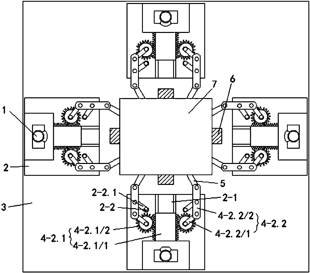
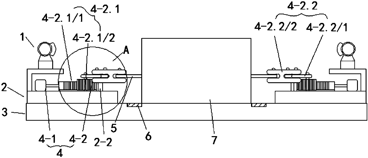
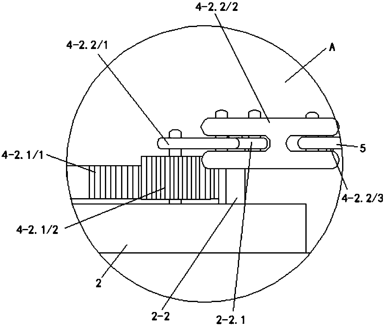
[0022] Such as Figure 1 to Figure 3 As shown, the present embodiment provides a video monitoring device for transformers, including a fixing base 3 for installing a transformer 7, and the fixing base 3 is respectively provided with mounting bases 2 corresponding to the four sides of the transformer 7, each installed The seat 2 is provided with a video monitoring component 1 and a transformer reset component 4. The video monitoring component 1 includes a camera for video acquisition and a microprocessor for data processing. The camera is electrically connected to a memory, and the microprocessor is electrically connected to the memory. And communicate with the upper computer, the transformer reset assembly 4 all includes the transmission mechanism 4-2 and the power mechanism 4-1 that drives the transmission mechanism 4-2, and the four sides of the transformer 7 are respectively symmetrically provided with two connecting rods 5, each connected The rods 5 are all connected with ...
Embodiment 2
[0027] This embodiment is further optimized on the basis of Embodiment 1, specifically:
[0028] The bottoms corresponding to the four sides of the transformer 7 on the fixed seat 3 are respectively provided with a pressure sensor 6 for detecting whether the transformer 7 is displaced, and the power mechanism 4-1 and the pressure sensor 6 are electrically connected with the PLC controller respectively, and when the pressure sensor 6. When the pressure is detected, the signal is transmitted to the PLC controller, and the PLC controller starts the corresponding power mechanism 4-1, thereby resetting the transformer 7 through the transmission mechanism 4-2, which has a high degree of automation and reduces the work intensity .
PUM
 Abstract
Description
Claims
Application Information
 - R&D Engineer
- R&D Manager
- IP Professional
- Industry Leading Data Capabilities
- Powerful AI technology
- Patent DNA Extraction
Browse by: Latest US Patents, China's latest patents, Technical Efficacy Thesaurus, Application Domain, Technology Topic, Popular Technical Reports.
© 2024 PatSnap. All rights reserved.Legal|Privacy policy|Modern Slavery Act Transparency Statement|Sitemap|About US| Contact US: help@patsnap.com