Low-temperature top-mounted ball valve seat structure and on-line maintenance disassembly method thereof

A valve seat and installation technology, which is applied in the direction of valve devices, cocks including cutting devices, mechanical equipment, etc., can solve the problems of time-consuming and labor-intensive rotation and tightening of the nut 4, affecting online maintenance work, and large working load of the spring 6, etc., to achieve Reduce energy consumption, improve work efficiency, and save costs

Pending Publication Date: 2018-03-06
CHINA HUANQIU CONTRACTING & ENG CO LTD
View PDF8 Cites 2 Cited by
  • Summary
  • Abstract
  • Description
  • Claims
  • Application Information

AI Technical Summary

Problems solved by technology

[0005] The above-mentioned traditional structure can realize the sealing function and meet the standard or the leakage level required by the customer. However, the spring 6 in this structure directly acts on the tightening nut 4. Due to the large working load of the spring 6, it is time-consuming and laborious to rotate the tightening nut 4. , it is difficult to operate in actual installation and use, and it will also affect online maintenance work. This structure is only suitable for small-diameter, low-pressure ultra-low temperature top-entry ball valves

Method used


Image

  • Low-temperature top-mounted ball valve seat structure and on-line maintenance disassembly method thereof
  • Low-temperature top-mounted ball valve seat structure and on-line maintenance disassembly method thereof

Examples


Embodiment Construction

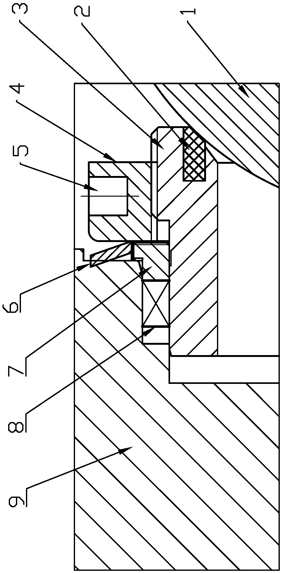
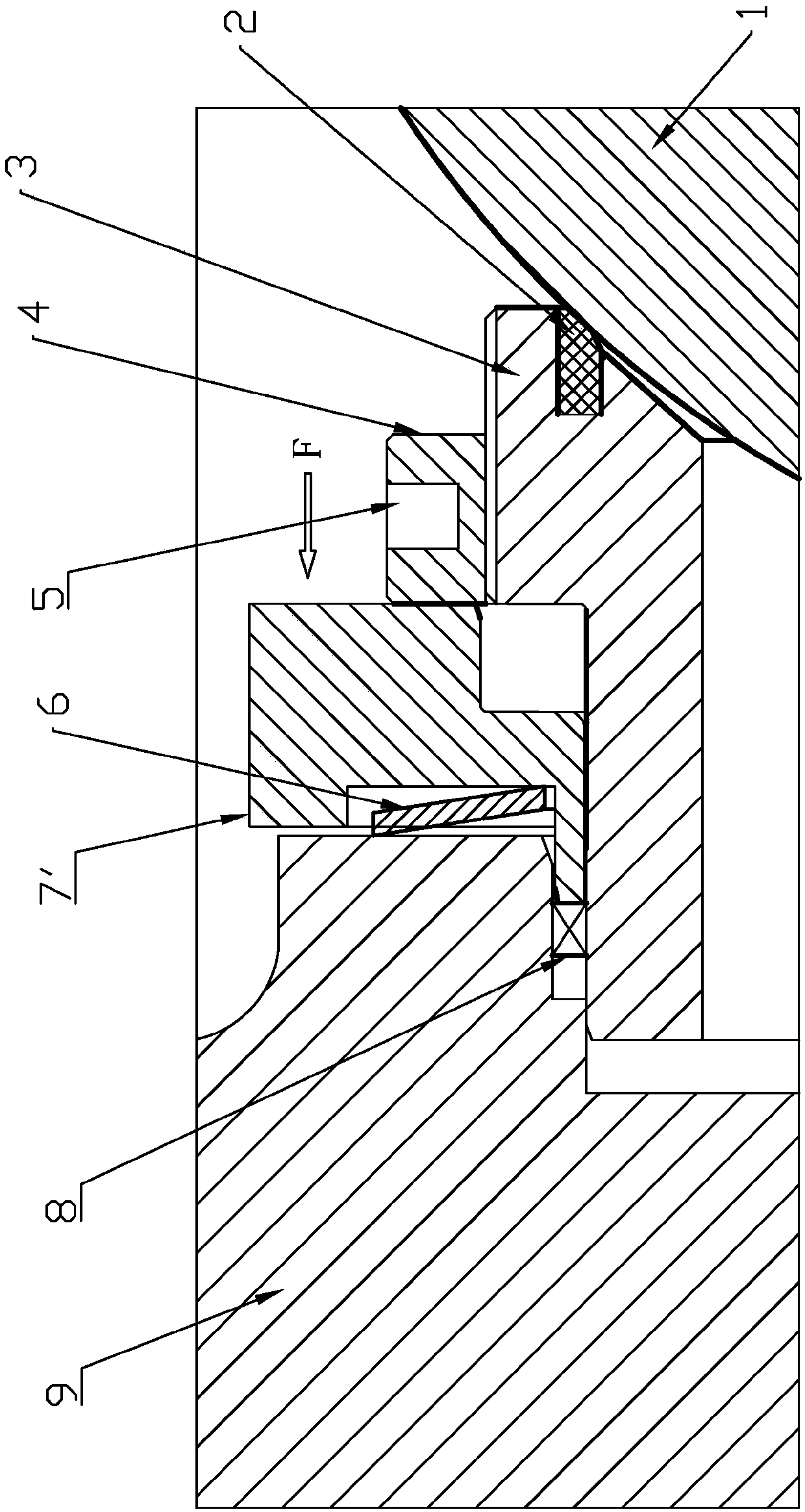
[0024] Such as figure 2 As shown, the present invention provides a low-temperature top-entry ball valve seat structure, which consists of a valve body 9, a ball 1, a seat assembly (including a seat metal ring 3, a seat sealing ring 2), a parallel nut 4, and a spring seat 7 ', spring 6, lip seal 8, wherein:

[0025] One end of the valve seat metal ring 3 extends into the valve body 9, and the other end forms a sealed connection with the ball 1 through the valve seat sealing ring 2;

[0026] The lip seal ring 8 is filled in the gap formed between the valve seat metal ring 3 and the valve body 9, and forms a sealed connection with the valve body 9;

[0027] The parallel nut 4 is threadedly connected to the outer side of the valve seat metal ring 3; a certain number of blind holes are opened around the parallel nut 4;

[0028] The spring seat 7' is sleeved outside the valve seat metal ring 3, and is located between the valve body 9 and the tightening nut 4, and its inner side e...


PUM


Abstract

The invention provides a low-temperature top-mounted ball valve seat structure and an on-line maintenance disassembly method thereof. The low-temperature top-mounted ball valve seat structure comprises a valve body, a ball body, a valve seat metal ring, a tightening nut, a spring base, a spring base, a spring and a sealing ring, wherein one end of the valve seat metal ring extends into the valve body, and the other end is connected with the ball body hermetically; the sealing ring is arranged in a clearance formed by the valve seat metal ring and the valve body, and is connected with the valvebody hermetically; the tightening nut is connected to the outer side of the valve seat metal ring through threads; the spring base sleeves the outer part of the valve seat metal ring, and is locatedbetween the valve body and the tightening nut; the inner side end surface of the spring base presses the sealing ring tightly; the outer diameter of the spring base exceeds the diameter of the tightening nut; and the spring is connected between the valve body and the spring base in a resisted manner. During assembly or disassembly, a disassembly force is provided for pushing the spring base to move for a certain distance, so that the spring base is out of contact with the tightening nut; and the tightening nut can be screwed or unscrewed easily, so that time and labor are saved.

Description

technical field [0001] The invention relates to a top entry ball valve which can be used in low temperature conditions, and the lowest temperature can reach -196°C. Background technique [0002] Cryogenic top entry ball valves are widely used in LNG receiving stations, LNG liquefaction stations, natural gas pipelines, oil refining, petrochemical and chemical plants. Because the medium in the low temperature environment has very high requirements on the performance of the material, the material is prone to shrinkage and deformation in the low temperature environment, thereby reducing the overall sealing performance of the valve. Any leakage or internal leakage of the low temperature medium will endanger human life and cause waste of resources. For example, the medium in the pipelines and storage tanks of the LNG receiving station is liquefied natural gas, the main component is methane, the chemical name is CH4, and there are a small amount of other components such as ethane C...

Claims


Application Information

Patent Timeline
Patent Type & Authority Applications(China)
IPC IPC(8): F16K5/06F16K5/08B23P19/02
CPCF16K5/061F16K5/08B23P19/02
Inventor 贾琦月王邦捷李玉龙陆卫球戴文柏黄永刚张鹏王秀彭涛明代永清杨茵
Owner CHINA HUANQIU CONTRACTING & ENG CO LTD
Why Eureka
Try Eureka