Down filling machine

A technology of down filling machine and main down filling table, which is applied in the field of down filling machines, can solve the problems of unreasonable design of down filling head, high labor intensity, waste of down resources, etc., so as to save weight sensor, reduce labor intensity, improve The effect of filling efficiency

Pending Publication Date: 2018-03-06
上海推罗智能设备科技有限公司
View PDF0 Cites 2 Cited by
  • Summary
  • Abstract
  • Description
  • Claims
  • Application Information

AI Technical Summary

Problems solved by technology

[0002] Before the appearance of the down filling machine, people usually filled the down manually. For example, the filling of down jackets, down pillows, down stuffed toys, etc. all relied on manual filling by workers, which was extremely labor-intensive and low in efficiency; The down filling machine is used instead of manual operation. The design of the down filling head of the existing down filling machine is unreasonable. When the down filling machine is filling down, the down filling head is in the cutting piece, and the down filling head is only equipped with a return air device. , the exhaust is not fast enough, the exhaust device is easy to be blocked after a period of time for down filling, and it is inconvenient to clean. , it is easy to bring out the down, which makes the down fly everywhere, wasting down resources and affecting the working environment; in addition, the existing down filling machines generally use weight sensors and weighing boxes to cooperate with weighing down to weigh the weight of the down to fill the down. The density of the down is easy to change when it enters the down filling gun from the mixing box. It is not easy to observe and find out whether the down is agglomerated when filling the down. Timely adjustment and maintenance are made to make the down sufficiently fluffy, and the use of weighing boxes and weight sensors makes the The cost is greatly increased and there will be time waiting for the weighing box to fill the down when filling the down, the efficiency is not high

Method used


Image

  • Down filling machine
  • Down filling machine
  • Down filling machine

Examples


Embodiment Construction

[0036] In order to make the object, technical solution and advantages of the present invention clearer, the present invention will be further described in detail below in conjunction with the accompanying drawings and embodiments. It should be understood that the specific embodiments described here are only used to explain the present invention, not to limit the present invention.

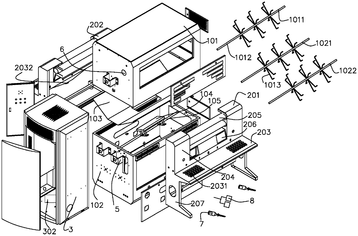
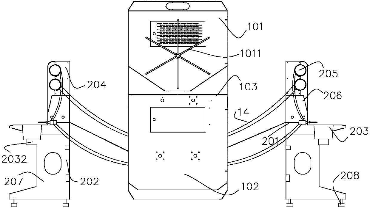
[0037] see Figure 1 to Figure 3 , a down filling machine, comprising a main box and two down filling platforms 201, 202, the down filling platform includes a main down filling platform 201 and a secondary down filling platform 202, and the two down filling platforms 201, 202 are set on both sides of the main box, and symmetrically arranged;

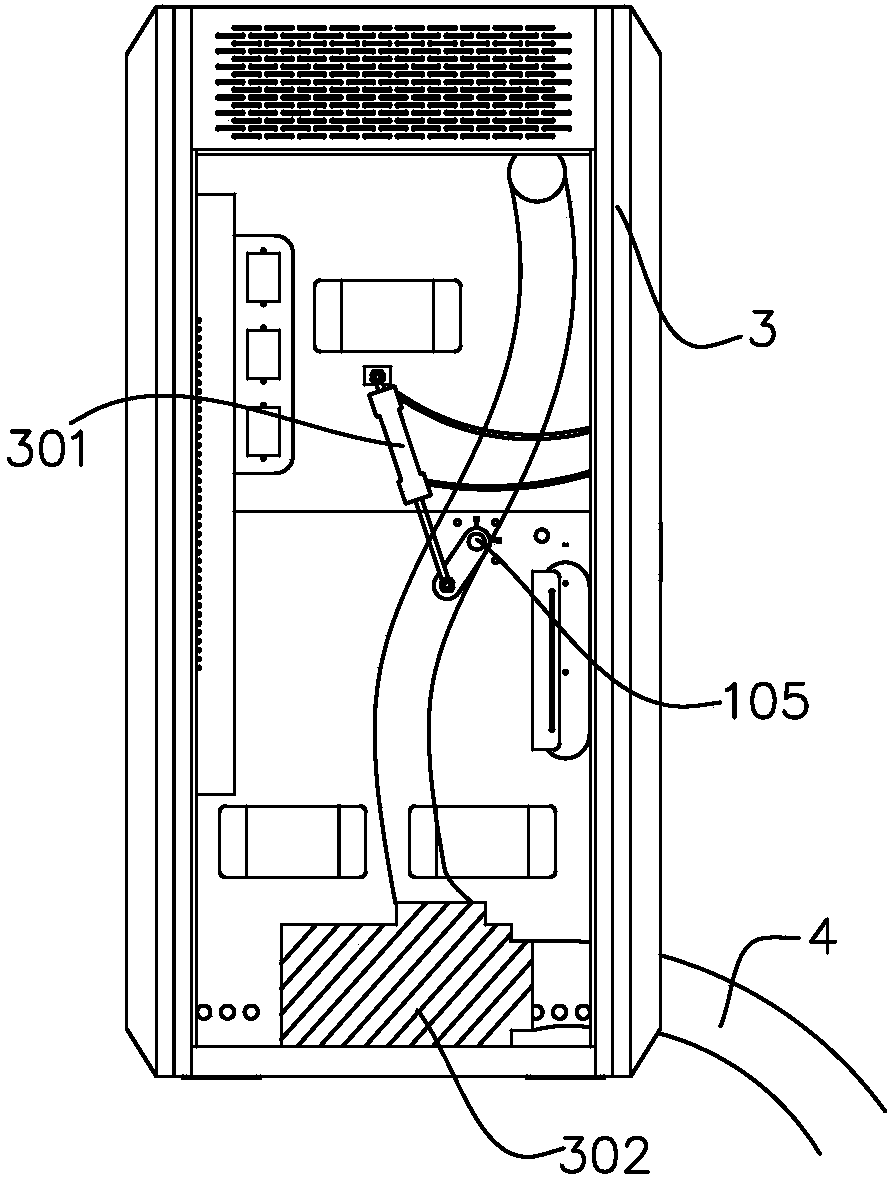
[0038] The outside of the main box body is provided with an electrical box 3, and the electrical box 3 is provided with a pull rod device 301, a blower 302, a first drive motor, a second drive motor, a third drive motor, a main PLC, a secondary PLC and conne...


PUM


Abstract

The invention provides a down filling machine, comprising a main box body and two down filling platforms, the down filling platform includes a main down filling platform and an auxiliary down filling platform, the down filling platform is arranged on the main box body Both sides are arranged symmetrically; the main box of the down filling machine is divided into upper and lower boxes, and the upper and lower boxes are respectively equipped with agitators driven by the drive motor to fully stir the down; the down filling table includes a rectangular Operating table, the upper side of the operating table is provided with a down filling bracket, and a plexiglass tube and a display are installed on the down filling bracket, one end of the plexiglass tube is connected with the down filling gun, and the other end of the plexiglass tube passes through the lower box. The down-feeding hoses are connected; the plexiglass tube cooperates with the down-filling gun, air pipe, and solenoid valve to be used under the control of PLC, which improves the down-filling efficiency and reduces the cost. The present invention can reduce labor intensity, improve production efficiency, and reduce costs. Simple, reasonable design, and strong practicability.

Description

technical field [0001] The invention relates to the technical field of filling equipment for down products, in particular to a down filling machine. Background technique [0002] Before the appearance of the down filling machine, people usually filled the down manually. For example, the filling of down jackets, down pillows, down stuffed toys, etc. all relied on manual filling by workers, which was extremely labor-intensive and low in efficiency; The down filling machine is used instead of manual operation. The design of the down filling head of the existing down filling machine is unreasonable. When the down filling machine is filling down, the down filling head is in the cutting piece, and the down filling head is only equipped with a return air device. , the exhaust is not fast enough, the exhaust device is easy to be blocked after a period of time for down filling, and it is inconvenient to clean. , it is easy to bring out the down, which makes the down fly everywhere, ...

Claims


Application Information

Patent Timeline
Patent Type & Authority Applications(China)
IPC IPC(8): B68G7/06
Inventor 王荣
Owner 上海推罗智能设备科技有限公司
Why Eureka
Try Eureka