
Rotary type new energy vehicle charging pile with heat dissipation apparatus

A new energy vehicle and cooling device technology, applied in electric vehicle charging technology, charging stations, electric vehicles, etc., to achieve the effects of convenient charging, improved heat dissipation performance, and extended service life

Active Publication Date: 2018-03-02
ANHUI KECHUANG NEWENERGY TECH CO LTD
View PDF6 Cites 18 Cited by
  • Summary
  • Abstract
  • Description
  • Claims
  • Application Information

AI Technical Summary

Problems solved by technology

[0005] In order to overcome the shortcomings of the existing technical solutions, the present invention provides a rotating new energy vehicle charging pile with a cooling device, which not only solves the problem of using the ordinary fixed charging pile, but also greatly increases the charging pile. Usability, increase construction efficiency, provide greater convenience for construction, improve the heat dissipation performance of charging piles, and facilitate people's installation and operation, and can effectively solve the problems raised by the background technology

Method used


Image

  • Rotary type new energy vehicle charging pile with heat dissipation apparatus
  • Rotary type new energy vehicle charging pile with heat dissipation apparatus
  • Rotary type new energy vehicle charging pile with heat dissipation apparatus

Examples


Embodiment

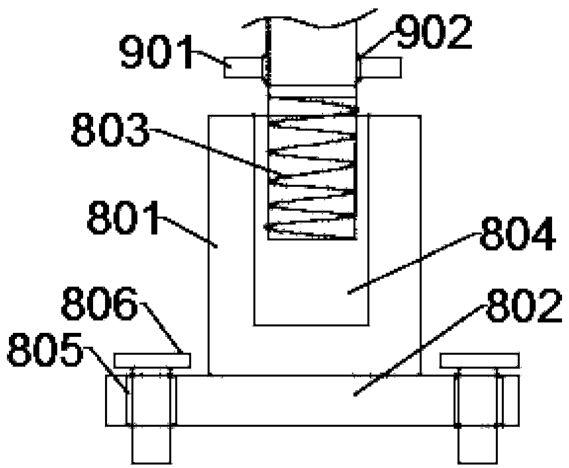
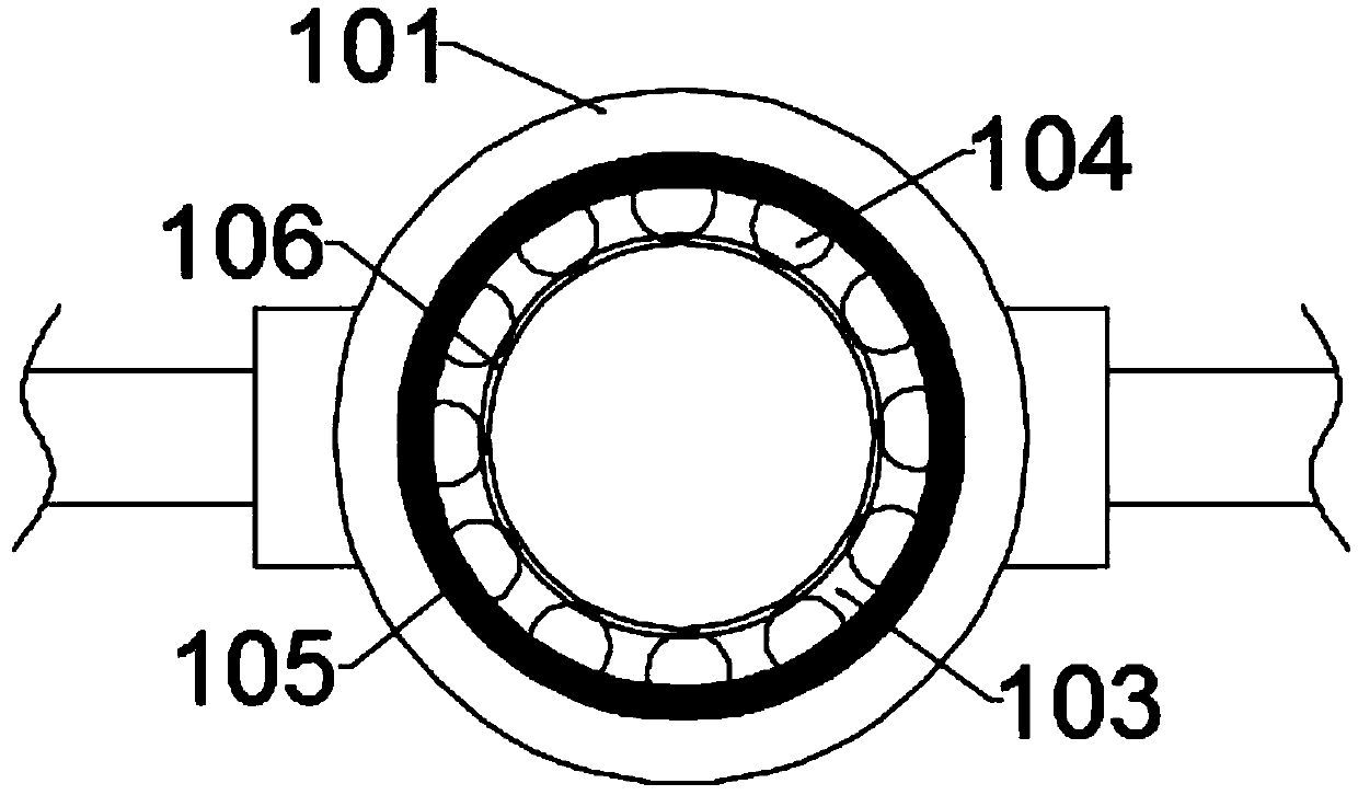
[0025] Such as figure 1 and figure 2 As shown, the present invention provides a rotary new energy vehicle charging pile with a cooling device, including a charging pile body 1, a rotating chassis 2 is provided at the bottom of the charging pile body 1, and the charging pile body 1 An umbrella frame 3 is installed on the top, wherein an umbrella plate seat 301 is arranged in the middle of the lower part of the umbrella frame 3, and the umbrella plate seat 301 is fixedly installed on the top plate of the charging pile body 1 through a supporting column 302. , can block rainwater, prevent rainwater from entering the charging pile body 1, and affect the normal operation of the equipment in the charging pile body 1, and the rotating chassis 2 is separated from the inner cavity 5 of the charging pile body 1 through the partition plate 4, And the inside of the rotating chassis 2 is connected with a rotating roller 7 by setting a rotating groove 6, wherein the rotating groove 6 is a...


PUM


Abstract

The present invention discloses a rotary type new energy vehicle charging pile with a heat dissipation apparatus. The rotary type new energy vehicle charging pile comprises a charging pile body. The bottom of the charging pile body is provided with a rotary chassis. The top of the charging pile body is provided with a rain shield rack. The rotary chassis is separated from an inner cavity of the charging pile body via a separator plate. The inside of the rotary chassis is provided with a rotary groove to be connected with a rotary roller. The axis of the rotary roller is connected with an uppercylinder of a telescoping column. The upper cylinder is connected with supporting frames via a supporting ring sleeve. The supporting frames are connected with the rotary chassis via pedestal plates.The top plate of the charging pile body under the rain shield rack is symmetrically equipped with two heat dissipation fans. Bottom ends of left and right side plates of the charging pile body are respectively equipped with heat dissipation grid plates. An outer side of each heat dissipation grid plate is provided with a protective arc plate. A charging gun and a wire reel are successively disposed over each protective arc plate from bottom to top. Air flow is accelerated through the heat dissipation fans and the heat dissipation grid plates, and the heat dissipation effect is increased.

Description

technical field [0001] The invention relates to the technical field of charging piles for new energy vehicles, in particular to a rotating charging pile for new energy vehicles with a cooling device. Background technique [0002] Among modern charging equipment, the new energy electric vehicle charging pile is a new type of charging equipment, its function is similar to that of a fuel dispenser in a gas station, it can be fixed on the ground or wall, and installed in public buildings (public buildings, shopping malls, public parking lots) etc.) and residential area parking lots or charging stations, can charge various types of electric vehicles according to different voltage levels. The input end of the new energy electric vehicle charging pile is directly connected to the AC power grid, and the output end is equipped with a charging plug for charging the electric vehicle. However, in the prior art, most of the charging piles for new energy vehicles are ordinary fixed charg...

Claims


Application Information

Patent Timeline
Patent Type & Authority Applications(China)
IPC IPC(8): B60L11/18H05K7/20
CPCB60L53/31H05K7/20909Y02T10/70Y02T10/7072Y02T90/12
Inventor 鹿婷婷
Owner ANHUI KECHUANG NEWENERGY TECH CO LTD
Learn More