
Sleeve, auxiliary device for mounting connection rod and mounting method of connection rod

An auxiliary device and connecting rod technology, which is applied in the field of medical equipment, can solve the problems of easy deviation from the correct route and low installation efficiency during the installation process, and achieve the effect of facilitating rehabilitation and reducing tissue damage and bleeding

Active Publication Date: 2018-02-27
SHANDONG WEIGAO ORTHOPEDIC DEVICE COMPANY
View PDF11 Cites 6 Cited by
  • Summary
  • Abstract
  • Description
  • Claims
  • Application Information

AI Technical Summary

Problems solved by technology

[0004] When the traditional auxiliary device for installing the connecting rod is used to install the connecting rod, the rod needs to be placed laterally (in the direction intersecting with the axis of the pedicle screw). During the installation process, it is easy to deviate from the correct route, so that one end of the connecting rod cannot be placed in the first position. In the U-shaped groove of the two pedicle screws, multiple rod insertion operations are required, and the installation efficiency is low; at the same time, when the traditional auxiliary device for installing connecting rods is applied to spinal minimally invasive surgery, it is difficult for doctors to operate. high demands

Method used


Image

  • Sleeve, auxiliary device for mounting connection rod and mounting method of connection rod
  • Sleeve, auxiliary device for mounting connection rod and mounting method of connection rod
  • Sleeve, auxiliary device for mounting connection rod and mounting method of connection rod

Examples


Embodiment Construction

[0039] In order to make the object, technical solution and advantages of the present invention clearer, the present invention will be further described in detail below in conjunction with the accompanying drawings and specific implementation methods. It should be understood that the specific embodiments described here are only used to explain the present invention, and do not limit the protection scope of the present invention.

[0040] It should be noted that when an element is referred to as being “fixed” to another element, it can be directly on the other element or there can also be an intervening element. When an element is referred to as being "connected to" another element, it can be directly connected to the other element or intervening elements may also be present. The terms "vertical," "horizontal," "left," "right," and similar expressions are used herein for purposes of illustration only and are not intended to represent the only embodiments.

[0041] Unless otherw...


PUM


Abstract

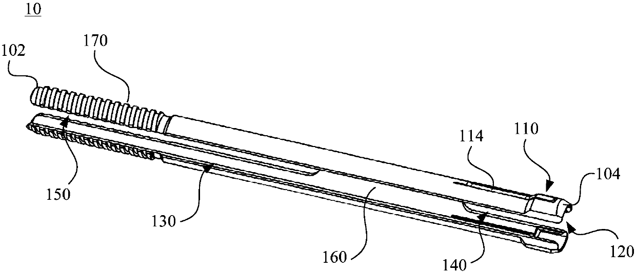
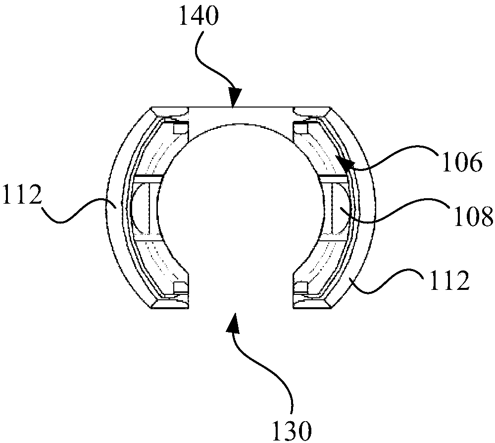
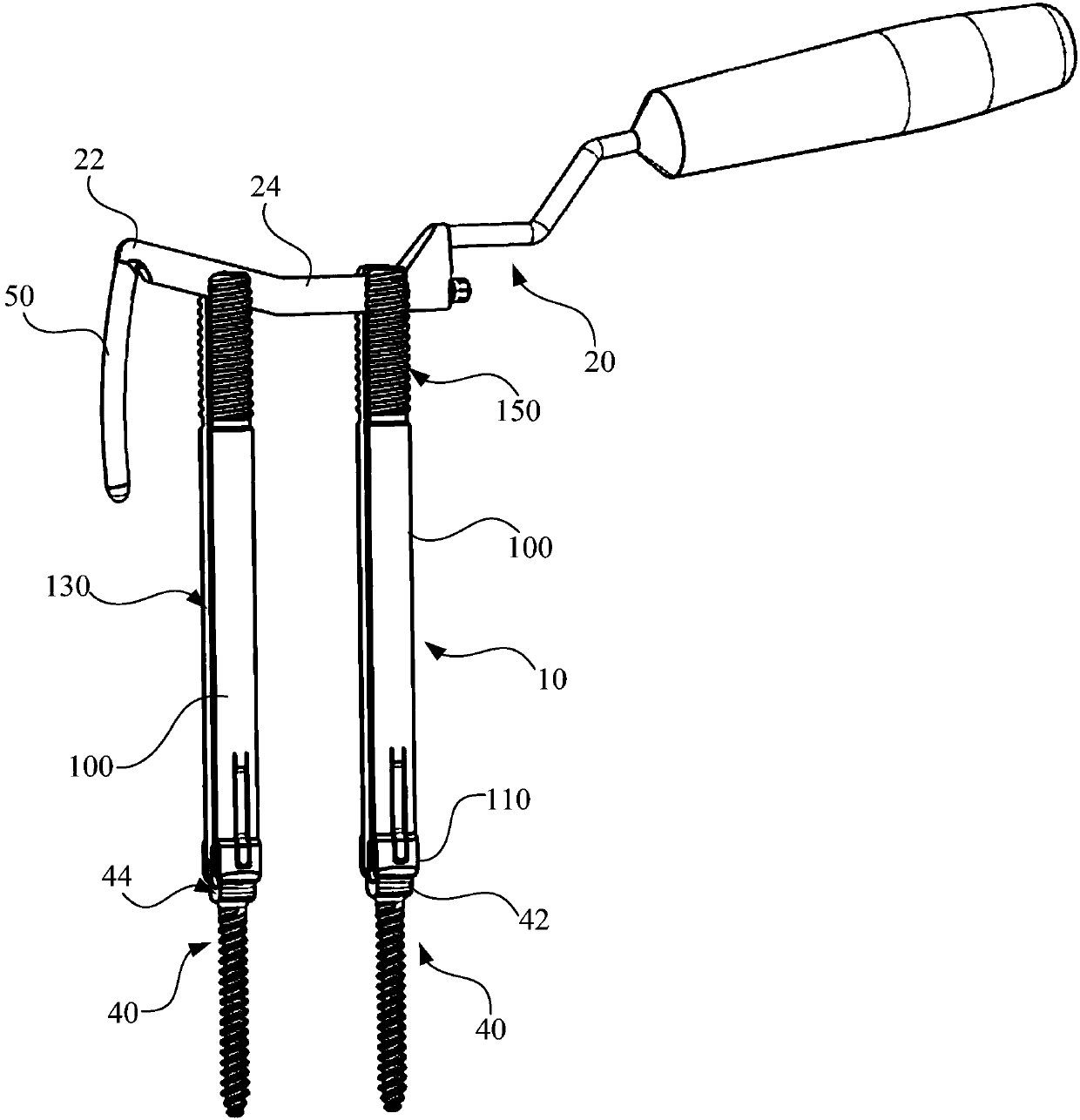
The invention discloses a sleeve, an auxiliary device for mounting a connection rod and a mounting method of the connection rod. The sleeve includes a sleeve body; the sleeve body includes a first endand a second end which are oppositely arranged, the second end of the sleeve body is provided with a clamp head for being connected with a tail cap of a pedicle screw in a buckle mode, a through holerunning through the first end and the second end is formed in the sleeve boy, and the side wall of the through hole is provided with a first guide through groove, a second guide through groove, a limit through groove and a guide wall, wherein the first guide through groove and the second guide through groove are formed oppositely; the first guide through groove runs through the sleeve body from the first end to the second end, the second guide through groove runs through the second end, the limit through groove runs through the first end, and the guide wall is arranged between the second guide through groove and the limit through groove. According to the sleeve, the auxiliary device for mounting the connection rod and the mounting method of the connection rod, all the guide characteristics of the sleeve body are adopted, so that the mounting accuracy of the connection rod is improved, and then the efficiency of spine minimally-invasive surgical operations is improved.

Description

technical field [0001] The invention relates to the technical field of medical instruments, in particular to a sleeve, an auxiliary device for installing a connecting rod and a method for installing the connecting rod. Background technique [0002] After years of clinical research, the spinal rod internal fixation system has become a relatively mature medical device for minimally invasive spinal surgery, which is widely used in the treatment of spinal injuries and related spinal diseases. Minimally invasive surgery has attracted more and more attention from doctors and patients because it can reduce intraoperative tissue damage and bleeding, reduce patients' surgical pain, and shorten wound healing time. [0003] In the spinal rod internal fixation system, it is often necessary to use an auxiliary device for installing the connecting rod to install the connecting rod. When the traditional auxiliary device for installing the connecting rod is used, its specific operation met...

Claims


Application Information

Patent Timeline
IPC IPC(8): A61B17/70
CPCA61B17/7083A61B17/7085
Inventor 徐峰邬春晖田康勇
Owner SHANDONG WEIGAO ORTHOPEDIC DEVICE COMPANY
Learn More