
Drilling machine for highway construction

A technology for road construction and drilling machines, which is applied in the direction of rotary drilling machines, drilling equipment and methods, construction, etc., which can solve problems such as short service life, impact on drilling accuracy, adjustment of height and left and right positions, and reduce work Intensity and difficulty, improvement of drilling work efficiency, effect of improving work efficiency

Inactive Publication Date: 2018-02-23
陕西天策智汇建筑科技有限公司
View PDF0 Cites 11 Cited by
  • Summary
  • Abstract
  • Description
  • Claims
  • Application Information

AI Technical Summary

Problems solved by technology

In the process of highway construction, drilling machines are often used for drilling operations. With the continuous development of my country's highway industry, a large number of drilling machines are needed. Since the current portable drilling machines are drilled manually, the circle of the drilling The degree is not uniform, and the perpendicularity to the surface to be drilled is also deviated. Therefore, a fixed method is required for portable drilling machines when drilling; general drilling equipment cannot easily adjust the height and left and right positions, resulting in the accuracy of drilling. Influence, and the operation process requires manual control, low degree of automation, low work efficiency, a large amount of dust will be generated during the drilling process, polluting the environment, and the overheating of the drill bit for a long time will cause damage to the drill bit, short service life, and increase the cost of use , In addition, manual handling or vehicle transportation is required when transferring drilling equipment, which is not convenient

Method used


Image

  • Drilling machine for highway construction

Examples


Embodiment Construction

[0011] The following will clearly and completely describe the technical solutions in the embodiments of the present invention with reference to the accompanying drawings in the embodiments of the present invention. Obviously, the described embodiments are only some, not all, embodiments of the present invention. Based on the embodiments of the present invention, all other embodiments obtained by persons of ordinary skill in the art without making creative efforts belong to the protection scope of the present invention.

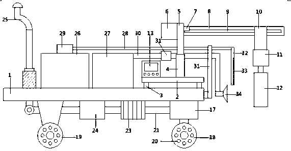
[0012] see figure 1 , in an embodiment of the present invention, a drilling machine for road construction, comprising a base 1, the upper right end of the base 1 is provided with a drilling machine base 2, and the four corners of the lower side of the drilling machine base 2 are provided with fixing columns 3. The bottom end of the fixed column 3 is fixed on the base 1. An electric telescopic rod 4 is provided on the upper side of the drilling machine base 2. ...


PUM


Abstract

The invention discloses a drilling machine for road construction, which comprises a base, a drilling machine base is arranged at the right end of the upper side of the base, fixing columns are arranged at the four corners of the lower side of the drilling machine base, and the bottom ends of the fixing columns are fixed on the base , there is an electric telescopic rod on the upper side of the base of the drilling machine, the movable end of the upper side of the electric telescopic rod is connected with a support rod, one side of the support rod is provided with a weighing block, the other side is connected with a cross bar, and the cross bar is set With a sliding mechanism, the drilling machine for highway construction of the present invention has a reasonable structural design, can realize precise drilling, has high drilling efficiency, can perform dust suction and water spraying operations, improves the environment, avoids pollution, and prolongs the working life of the drill bit. The service life ensures long-term continuous work. The entire working process is controlled by the control box, which has a high degree of automation and saves time and effort. In addition, it is convenient for quick transfer of drilling machinery, which improves work efficiency and has small vibration during movement.

Description

technical field [0001] The invention relates to a road machine, in particular to a drilling machine for road construction. Background technique [0002] Highway engineering refers to the investigation, measurement, design, construction, maintenance and management of highway structures. Highway engineering structures include: subgrades, road surfaces, bridges, culverts, tunnels, drainage systems, safety protection facilities, greening and traffic monitoring facilities, as well as houses, workshops and other service facilities used for construction, maintenance and monitoring. High-quality projects not only have good design, but also depend on the quality of construction to a greater extent. In construction, materials, equipment and operation are the main links to ensure product quality. All construction must strictly abide by each construction specification. In the process of highway construction, drilling machines are often used for drilling operations. With the continuou...

Claims


Application Information

Patent Timeline
Patent Type & Authority Applications(China)
IPC IPC(8): E21B7/02E21B7/04E21B15/00E21B44/00E21B21/015E21B3/02
CPCE21B7/022E21B3/02E21B7/04E21B15/00E21B21/015
Inventor 高莎
Owner 陕西天策智汇建筑科技有限公司
Learn More