Medical bone drill

A bone drill and drill bit technology, which is applied in the medical field, can solve problems such as excessive force, affecting surgery, and difficult control of force, and achieve the effects of protecting bones, avoiding excessive movement, and improving versatility

Inactive Publication Date: 2018-02-23
周逸
View PDF7 Cites 1 Cited by
  • Summary
  • Abstract
  • Description
  • Claims
  • Application Information

AI Technical Summary

Problems solved by technology

There are the following problems in the existing bone drills: first, most of the existing drill bits cannot be replaced, and in a small number of better bone drills, the replacement is not convenient; When drilling, the force is not easy to control, and sometimes the force is too large, and the drill is too deep, which will affect the operation

Method used


Image

  • Medical bone drill
  • Medical bone drill
  • Medical bone drill

Examples


specific Embodiment 1

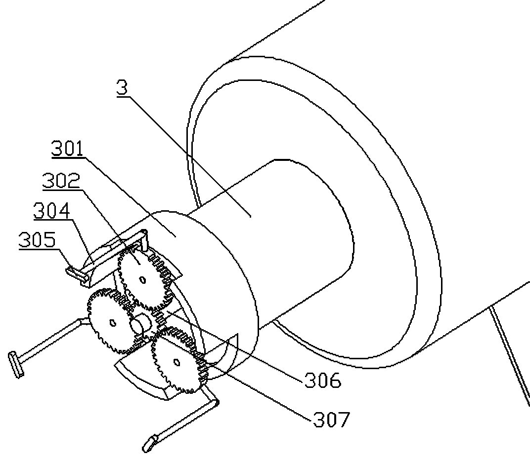
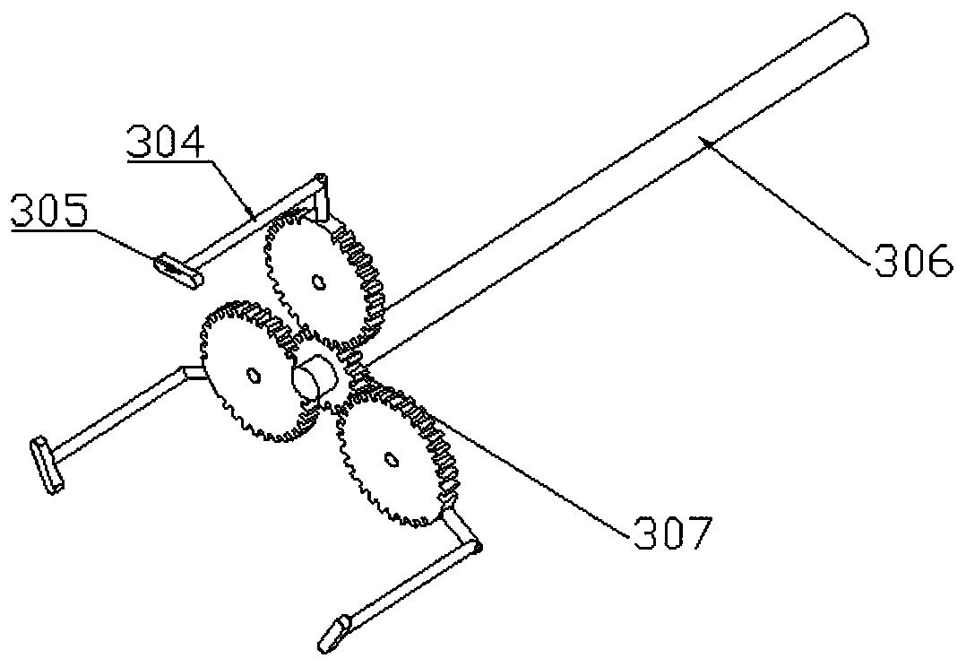
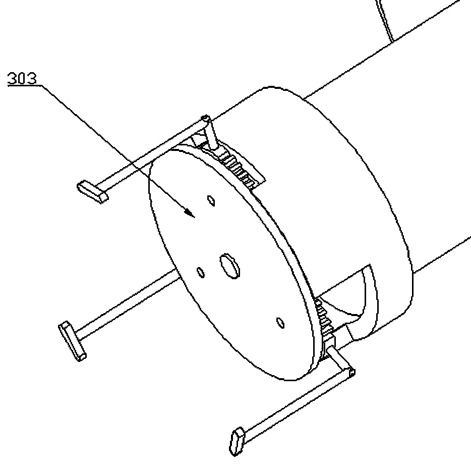
[0026] Specific embodiment 1: This embodiment discloses a kind of medical bone drill, comprises handle 1, drill body 2 and drill bit 4, and handle 1 and drill bit are respectively fixed on the drill body, is provided with motor 201 on the drill bit, described The drill bit is provided with a detachable connection between the fixed seat 3 and the drill bit 4. The fixed seat includes a recessed fixed seat shell 301. The middle of the fixed seat shell 301 is provided with a rotating rod 306 connected to the motor 201. The end of the rotating rod Be provided with driving gear 307, driving gear and fixed gear tooth and 302, fixed gear is three, and each fixed gear is provided with the fixed rod 304 that is distributed parallel to the axial direction of fixed gear, and fixed end is provided with fixed head 305, through The motor rotates the rotating rod 306 to drive the driving gear, the driving gear drives the fixed gear, the fixed gear drives the rotating rod to rotate, and the fix...

specific Embodiment 2

[0028] Specific embodiment 2: the difference between it and specific embodiment 1 is that the drill bit is different, and specifically also includes a first rotating seat connected to the drill pipe, the rotating seat is provided with a movable rod 407, and the end of the movable rod is fixed with a movable block 409 The clamping column is fixedly connected with a connecting rod 402, the end of the connecting rod is integrally formed with a connecting piece 403, the connecting piece 403 is fixedly connected with a second swivel seat, the second swivel seat is provided with a movable groove 408, and the movable block is located in the movable groove, And can only move up and down along the movable groove, the bottom of the movable groove is provided with a channel for the movable column to pass through, the first rotating seat and the second rotating seat are connected by an elastic member, and the elastic member is in a compressed state.

[0029] The elastic member is a spring ...


PUM


Abstract

The invention discloses a medical bone drill and belongs to the field of medical equipment. The universality problem of the bone drill is mainly solved. The medical bone drill comprises a handle, a drill body and a drill bit, wherein the handle and the drill bit are fixed to the drill body, and a motor is arranged on the drill bit. The medical bone drill is characterized in that a fixing seat is arranged on the drill bit and is detachably connected with the drill bit, the a fixing seat comprises a recessed fixing seat shell, a rotary rod connected with the motor is arranged in the middle of the fixing seat shell, a driving gear is arranged at the tail end of the rotary rod and is matched with fixed gears, the number of the fixed gears is three, fixing rods parallelly distributed in the axial direction of the fixed gears are arranged on the fixed gear, a fixing head is arranged at the tail end for fixing, the rotary rod drives the driving gear through the motor, the driving gear drivesthe fixed gears, the fixed gears drive the rotary rod to rotate, and the fixed gears and the driving gear are fixed to a base. The drill bit comprises a clamping column and a drill rod, wherein the clamping column is clamped in a fixing rod.

Description

technical field [0001] The medical field of the present invention is specifically a medical bone drill. Background technique [0002] Bone drills are often used in medicine, and are often used in neurosurgery, cardiothoracic surgery, orthopedics, burns, etc. The existing bone drills are usually electric, and a motor controls the rotation of the drill bit to drill on the corresponding bone. hole. There are the following problems in the existing bone drills: first, most of the existing drill bits cannot be replaced, and in a small number of better bone drills, the replacement is not convenient; When drilling, the force is not easy to control, and sometimes the force is too large, and the drilling is too deep, which will affect the operation. Contents of the invention [0003] In order to solve the existing problems, the present invention provides a medical bone drill, including a handle, a drill body and a drill bit, the handle and the drill bit are respectively fixed on t...

Claims


Application Information

Patent Timeline
Patent Type & Authority Applications(China)
IPC IPC(8): A61B17/16
CPCA61B17/1615A61B17/1622A61B17/1624A61B17/1626
Inventor 师新虎
Owner 周逸
Why Eureka
Try Eureka