Electric cabinet with square tube frame

A tube frame and electrical cabinet technology, applied in electrical components, substation/distribution device housing, substation/switch layout details, etc., can solve the problems of insufficient stocking, long procurement cycle, high cost, and achieve a wide range of applications and easy quality. Guaranteed, the effect of short construction time

Inactive Publication Date: 2018-02-16
扬州市庆源电气成套设备有限公司
View PDF0 Cites 2 Cited by
  • Summary
  • Abstract
  • Description
  • Claims
  • Application Information

AI Technical Summary

Problems solved by technology

[0002] With the increasing demand for electrical cabinets, electrical cabinets made of special profiles sometimes have a lot of modular square holes and round holes. Many holes are wasted when the profiles are punched before.
The special frame profiles are expensive, the procurement cycle is long, and the investment in rolling machinery is expensive at one time, and the requirements for debugging and production technicians are high.
There are many times, due to insufficient stocking of special frame profiles in the warehouse, resulting in production stoppage
Moreover, the existing electrical frame has high cost due to its unreasonable structure. In order to reduce the cost and meet the needs of customers, a square tube frame electrical cabinet was born.

Method used


Image

  • Electric cabinet with square tube frame
  • Electric cabinet with square tube frame
  • Electric cabinet with square tube frame

Examples


Embodiment Construction

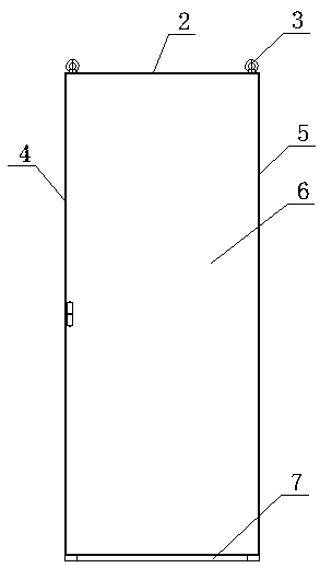
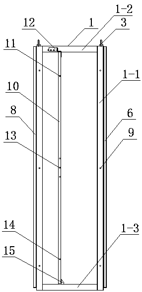
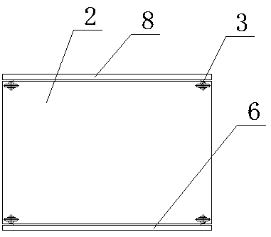
[0012] Such as figure 1 As shown in -6, the square tube frame electrical cabinet includes a square tube frame 1 welded by square tubes, and the left side panel 4, right side panel 5, rear door panel 8, top panel 2 and bottom panel 7 are connected to the square tube frame 1 , the front door panel 6 is also hinged on the square tube frame 1, and the suspension rings 3 are respectively fixedly connected on the four corners of the top plate 2.

[0013] The square tube frame 1 is welded by four square tube vertical bars 1-1, four square tube upper cross bars 1-2, four square tube lower bar 1-3, and four square tube vertical bar positions 1-1 On the four corners of the square tube frame 1, and on the outside of the left side plate 4 and the right side plate 5, the upper ends of the four square tube vertical bars 1-1 are connected by four square tube upper cross bars 1-2, four The lower end of the root square tube vertical bar 1-1 is connected by four square tube lower cross bars 1-...


PUM


Abstract

Square tube frame electrical cabinet, involving the field of electrical equipment, including a square tube frame welded by square tubes, on which the left side panel, right side panel, rear door panel, top panel and bottom panel are connected, and on the square tube frame The front door panel is hinged, and the four corners of the top panel are respectively fixed and connected to the lifting rings; the square tube frame is welded by four square tube vertical bars, four square tube upper rails, and four square tube lower rails. The upper, middle and lower parts of the pipe vertical rods are all equipped with cabinet holes, the upper ends of the four square pipe vertical rods are connected by four square pipe upper cross bars, and the lower ends are connected by four square pipe lower cross bars; at the left and right sides of the square pipe frame The two sides are respectively connected to the mounting plate, the upper end of each mounting plate is connected with the corresponding upper cross bar of the square tube through the upper bracket, and the lower end of each mounting plate is connected with the corresponding lower cross bar of the square tube through the lower bracket. The upper part is provided with an upper installation hole, the middle part is provided with three middle installation holes, and the lower part is provided with a lower installation hole. The invention has low cost and reasonable structure.

Description

technical field [0001] The invention relates to the field of electrical equipment, in particular to the structure of an electrical cabinet. Background technique [0002] With the increasing demand for electrical cabinets, electrical cabinets made of special profiles sometimes have a lot of modular square holes and round holes. Many holes are wasted if the profiles are punched before. Special frame profiles are expensive, and the procurement cycle is long. If you invest in rolling machinery yourself, the one-time cost is expensive, and the requirements for debugging and production technicians are high. There are many times when the production stops due to insufficient stocking of special frame profiles in the warehouse. Moreover, the existing electrical frame has high cost due to its unreasonable structure. In order to reduce the cost and meet the needs of customers, a square tube frame electrical cabinet was born. Contents of the invention [0003] The object of the pres...

Claims


Application Information

Patent Timeline
Patent Type & Authority Applications(China)
IPC IPC(8): H02B1/01H02B1/044H02B1/30
CPCH02B1/01H02B1/044H02B1/30
Inventor 龚忠永
Owner 扬州市庆源电气成套设备有限公司
Why Eureka
Try Eureka