
Novel fixed wing unmanned aerial vehicle

An unmanned aerial vehicle and fixed-wing technology, applied in the field of new fixed-wing unmanned aerial vehicles, can solve the problems of damage to the airborne equipment, poor shock absorption effect, economic loss, etc., to ensure high efficiency and success rate, and route stability Improved performance and the effect of avoiding bouncing

Inactive Publication Date: 2018-02-16
UNIV FOR SCI & TECH SICHUAN
View PDF0 Cites 0 Cited by
  • Summary
  • Abstract
  • Description
  • Claims
  • Application Information

AI Technical Summary

Problems solved by technology

[0003] The structure of the existing unmanned fixed-wing operation aircraft basically adopts the front-pull engine installation mode, and there is only one vertical tail, which greatly limits the route stability of the aircraft during operation
The landing gear is the guarantee for the landing of the fixed-wing unmanned aircraft. The shock absorption effect of the landing gear will also affect the vibration amplitude when the unmanned aerial vehicle lands. If the meeting is too large, the crash will damage the airborne equipment, which will not only affect the smooth completion of the task, but also cause economic losses
At present, the existing technology mainly absorbs shocks by adding cushions or wheels, and the shock absorption effect is poor, and the general rear landing gear is two wheels connected to a rod, so that the UAV may land when it lands. Rollover will occur due to an unbalanced wheel landing on the ground. Even if some landing gears use springs to absorb shock, the expansion and contraction of the springs will cause the fixed-wing unmanned aircraft to bounce when landing

Method used


Image

  • Novel fixed wing unmanned aerial vehicle
  • Novel fixed wing unmanned aerial vehicle

Examples


Embodiment Construction

[0017] The present invention will be further described below with reference to the accompanying drawings and embodiments, and the mode of the present invention includes but not limited to the following embodiments.

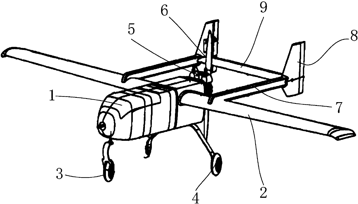
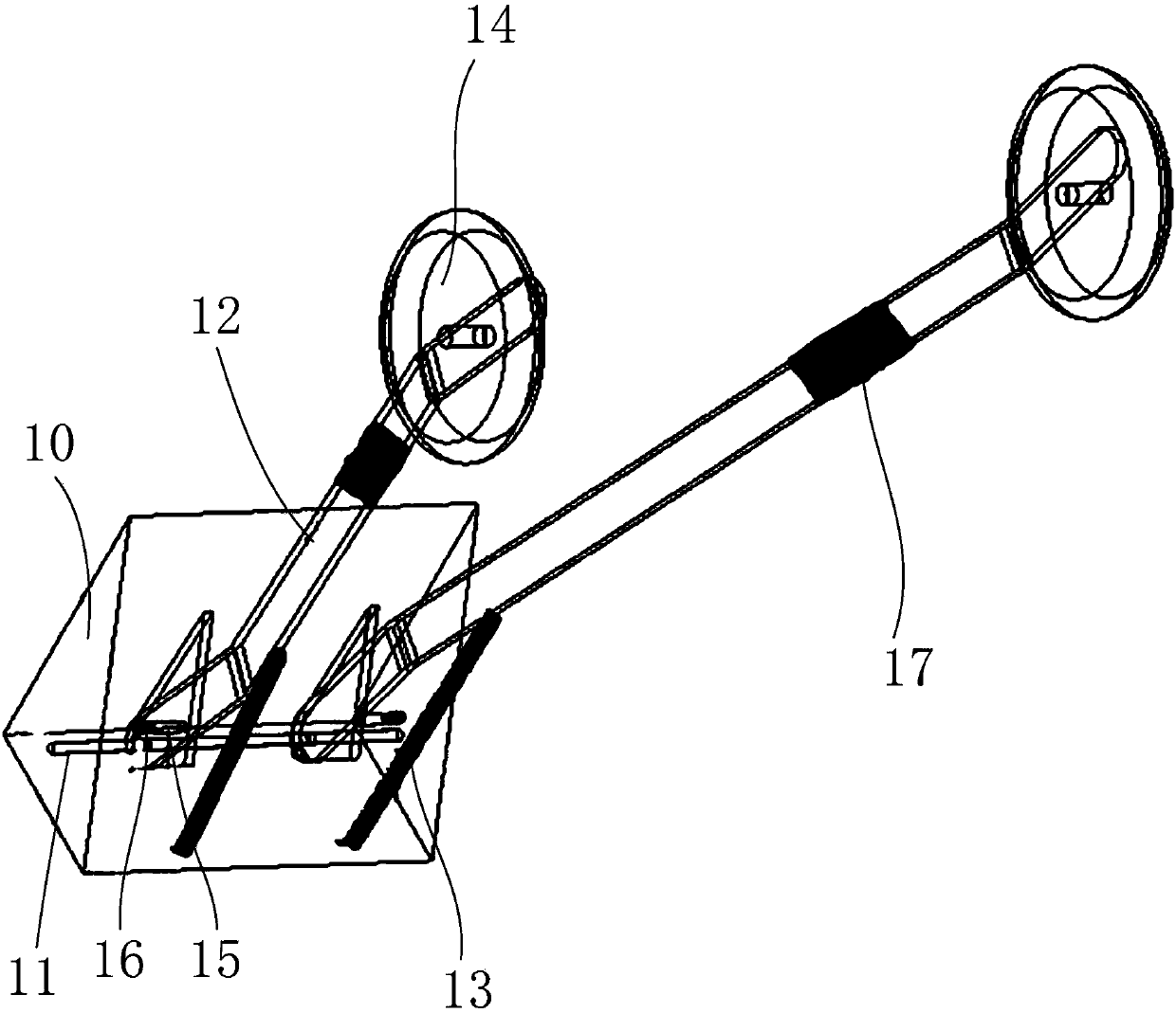
[0018] Such as figure 1 with 2 As shown, a new type of fixed-wing UAV includes a fuselage 1, a wing 2, a front landing gear 3, a rear landing gear 4, an engine 5, and a propeller 6; And be used for rear landing gear 4 is installed on the mounting part 10 on the unmanned aerial vehicle, be arranged on the fixed cross bar 11 of mounting part 10 inside, and the shock absorbing mechanism that distributes symmetrically along the central axis of mounting part 10; The shock absorbing mechanism includes through The fixed cross bar 11 is connected to the mounting part 10 and the supporting leg 12 protrudes obliquely backward from the bottom of the mounting part 10. One end is connected to the bottom of the mounting part 10 and the other end is connected to the upper part ...


PUM


Abstract

The invention discloses a novel fixed wing unmanned aerial vehicle including a fuselage, wings arranged on two sides of the fuselage, a front landing gear, a rear landing gear, an engine arranged at the rear end of the fuselage, and a propeller arranged at the rear end of the fuselage, wherein the front landing gear and the rear landing gear are arranged at the bottom of the fuselage; each wing isprovided with a connecting rod, the tail end of each connecting rod is provided with a vertical tail wing, and a horizontal tail wing is arranged between the vertical tail wings; the rear landing gear includes a mounting part, a fixed cross rod arranged in the mounting part, and damping mechanisms symmetrically distributed along the central axial surface of the mounting part, wherein the mountingpart is connected with the bottom of the fuselage and is used for mounting the rear landing gear on the unmanned aerial vehicle; each damping mechanism includes support legs, externally-placed springs and wheels, wherein the support legs are connected with the mounting part through the fixed cross rod and inclinedly extend backwards from the bottom of the mounting part, one end of each external spring is connected with the bottom of the mounting part, the other end of each external spring is connected with the upper part of each support leg, the external springs are pulled up when the unmanned aerial vehicle lands, and the wheels are connected with the lower ends of the support legs through wheel shaft structures; the front end of the fuselage is provided with a video camera.

Description

technical field [0001] The invention relates to the field of shock absorbers for unmanned aerial vehicles, in particular to a novel fixed-wing unmanned aerial vehicle. Background technique [0002] The fixed-wing unmanned aircraft has the characteristics of fast flight speed, relatively economical, large carrying capacity, and long range. ground. Fixed-wing unmanned aerial vehicles have been widely used in power line inspection, highway monitoring, simulated flight and other fields, for monitoring evidence collection and special location observation, etc., and can realize real-time transmission of on-site images, which is an important way to obtain information tool. In addition, fixed-wing unmanned aircraft toys are also loved by many players. [0003] The structure of the existing unmanned fixed-wing operation aircraft basically adopts the front-pull engine installation mode, and all have only one vertical tail, which greatly limits the route stability of the aircraft du...

Claims


Application Information

Patent Timeline
Patent Type & Authority Applications(China)
IPC IPC(8): B64C39/02B64C25/62
CPCB64C25/62B64C39/02B64U10/25B64U50/13
Inventor 郭蔼玲
Owner UNIV FOR SCI & TECH SICHUAN
Learn More