
Metal pipe welding device for building construction

A technology of metal pipes and welding devices, which is applied in welding equipment, metal processing, metal processing equipment, etc., can solve problems such as difficulty in matching, affecting weld integrity and welding quality, and large usage of welding rods, so as to reduce the usage , improve resource utilization, improve the effect of welding efficiency

Active Publication Date: 2018-02-16
上海中巽科技股份有限公司
View PDF6 Cites 1 Cited by
  • Summary
  • Abstract
  • Description
  • Claims
  • Application Information

AI Technical Summary

Problems solved by technology

[0002] At present, in building construction, various metal pipes, such as round pipes, square pipes, etc., are needed. At the connection position of the pipes, the connection is fixed by spot welding first, and then the connection gap is fully welded to achieve the connection. It is necessary to preheat the pipe beforehand to ensure the welding quality of the weld position. During the welding process, it is necessary to manually rotate the welding torch to weld the connection seam, and the gap between the connection seam has been fixed in advance, so all the gaps are welded by welding. For filling, the amount of welding rod used is large, and the speed of manual rotation of the welding torch needs to match the welding speed. It is difficult to fully cooperate with people alone, which affects the integrity and welding quality of the weld, especially for pipe connections that need to withstand pressure.

Method used


Image

  • Metal pipe welding device for building construction

Examples


Embodiment Construction

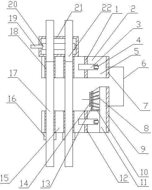
[0020] The welding device for building construction metal pipes of the present invention is realized in this way. When in use, when welding two metal pipes, first connect the drive rod (19) with the external motor and place it on the semicircular ring (10). Into a certain amount of welding slag, one end of the first metal pipe passes through the first connection cavity (11) and is placed between the arc plate (13) and the cover plate (9), and one end of the second metal pipe passes through the second connection cavity (5) Place between the arc plate (13) and the cover plate (9), and leave a certain gap between one end of the first metal pipe and one end of the second metal pipe, and push the two compression rods (3), The first metal tube and the second metal tube are respectively compressed and fixed, and a certain gap is left between one end of the first metal tube and the second metal tube and the plurality of cathode rods (8) respectively, and the first metal tube and the sec...


PUM


Abstract

The invention discloses a metal pipe welding device for building construction, and the welding device is a device for carrying out complete and continuous welding on connection gaps through the rotation of pipes and for carrying out welding by cooperating with a situation that the pipes are pressed against and close to each other. The metal pipe welding device for the building construction is characterized in that a fixed box body is arranged on a main support plate, one end of a driving rod is arranged on the inner wall of one side of the fixed box body through a bearing, and the other end ofthe driving rod passes through the other side of the fixed box body through the bearing. Worm wheels are arranged on the driving rod and are located in the fixed box body, and two guide sleeves are respectively arranged on the main support plate and are parallel to each other. Two screws respectively penetrate through the fixed box body, and one ends of the two screws are respectively installed in the two guide sleeves on the main support plate. The screws are meshed with the worm wheels, a main vertical plate is arranged on the main support plate and is located on one side of the fixed box body. A through hole is formed in the main vertical plate, a baffle plate is arranged at one end of the main support plate, a second connecting cavity is arranged between the baffle plate and the mainvertical plate, and one end of a pressing rod passes through the through hole in the main vertical plate and is arranged between the main vertical plate and the baffle plate.

Description

Technical field [0001] The invention provides a metal pipe welding device for building construction, which relates to a device for welding metal pipes at butt positions during building construction, and belongs to the field of building construction. In particular, it relates to a device for performing complete and continuous welding on the connecting gap through the rotation of the pipe, and the device is matched with the pipe being squeezed close to each other for welding. Background technique [0002] At present, various metal pipes, such as round pipes, square pipes, etc., are used in construction. At the connection position of the pipes, the fixed connection is made by spot welding first, and then the connection gap is fully welded to achieve the connection. It is necessary to preheat the pipe to ensure the welding quality of the welding seam. During the welding process, the welding torch needs to be manually rotated to weld the connecting seam. The gap of the connecting seam...

Claims


Application Information

Patent Timeline
IPC IPC(8): B23K31/02
CPCB23K31/027B23K2101/06
Inventor 不公告发明人
Owner 上海中巽科技股份有限公司
Learn More