
A minimally invasive bone fixation cable implantation device and bone fixation method thereof

A technology for fixing cables and implanting equipment, which is applied in fixers, medical science, surgery, etc. It can solve the problems of large installation trauma, complicated fixation surgery, and the inability of the patient to realize the platform of the bracket, so as to achieve small trauma and high puncture pass rate , the effect of increasing the range of movement

Inactive Publication Date: 2020-12-04
赵郁
View PDF4 Cites 0 Cited by
  • Summary
  • Abstract
  • Description
  • Claims
  • Application Information

AI Technical Summary

Problems solved by technology

[0005] The technical problem to be solved by the present invention is: to overcome the technical problems that the bracket in the prior art cannot allow the patient to realize the platform, and at the same time, the installation trauma is large and the fixation operation is complicated, and to provide a minimally invasive bone fixation cable implantation device and its bone fixation method

Method used


Image

  • A minimally invasive bone fixation cable implantation device and bone fixation method thereof
  • A minimally invasive bone fixation cable implantation device and bone fixation method thereof
  • A minimally invasive bone fixation cable implantation device and bone fixation method thereof

Examples


Embodiment Construction

[0031] The present invention is described in further detail now in conjunction with accompanying drawing. These drawings are all simplified schematic diagrams, which only illustrate the basic structure of the present invention in a schematic manner, so they only show the configurations related to the present invention.

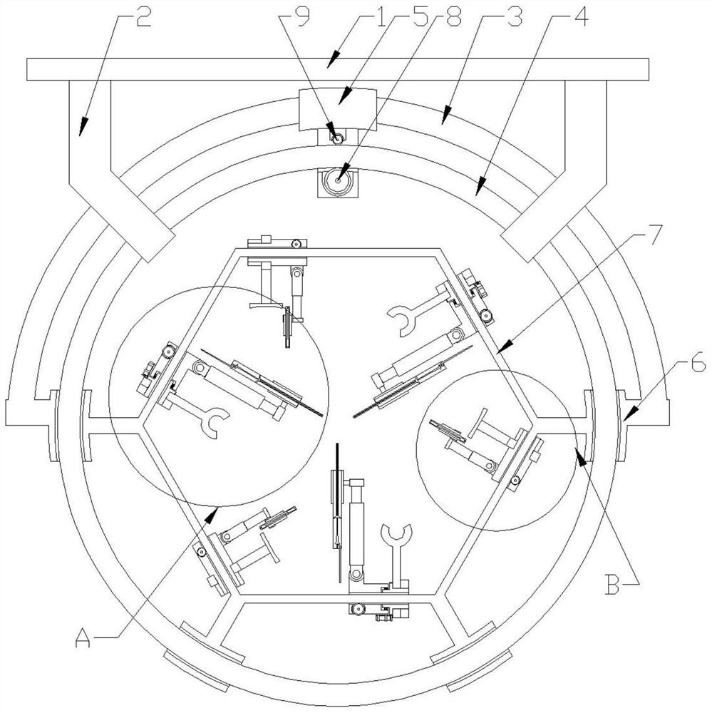
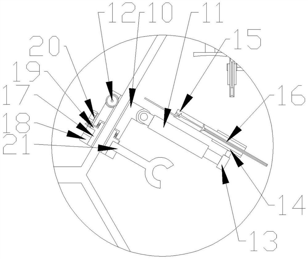
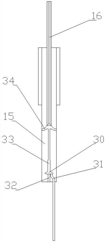
[0032] Such as Figure 1~3As shown, a minimally invasive bone fixation cable implantation device includes a connecting base, a driving outer frame, a sliding inner frame, a supporting inner frame, and an implantation mechanism and a wire pulling mechanism arranged on the supporting inner frame; wherein the sliding The inner frame is an annular ring structure, and the connecting base is connected to the sliding inner frame through at least one connecting arm; a plurality of sliding sleeves are arranged in an annular array on the sliding inner frame, and the sliding sleeves can slide along the sliding inner frame, and the sliding sleeve array The deployment ang...


PUM


Abstract

The invention relates to minimally invasive type bone fixing cable implanting equipment and a bone fixing method thereof. The equipment comprises a sliding inner frame, and sliding sleeves are arranged on the sliding inner frame in a ring array mode; a driving outer frame is connected to the sliding sleeves located at the two ends of the sliding sleeve array; a support inner frame is connected tothe inner wall of the sliding grooves; a rolling mechanism is arranged on the driving outer frame, the driving outer frame rotates relative to the sliding inner frame, and then the support inner frameis driven to rotate; an implanting mechanism comprises a sliding block A; the sliding block A is in swinging connection with a spray pipe which comprises a spray pipe body and a spray needle, the spray needle is fixed to the end of the spray pipe body, the spray pipe body is internally provided with a feed pipe used for containing steel wires, an air inlet pipe enters a machine body, and an exhaust cavity provides pressure; a cable drawing mechanism comprises a sliding block B which is in swinging connection with a wiring pipe; the wiring pipe comprises a suction pipe of a gradual contractionstructure and an attraction pipe coaxially connected to the necking end of the suction pipe; the position is adjusted through the sliding block A and the sliding block B, and by making the spray pipeand wiring pipe penetrate into the human body, threading of the elastic steel wires is achieved.

Description

technical field [0001] The invention relates to an implantation device and a method for using the auxiliary fixation equipment used for bone healing after bone surgery, in particular to a minimally invasive bone fixation cable implantation device and a bone fixation method. Background technique [0002] In the process of orthopedic treatment such as fractures, various brackets are often used to penetrate the skin surface after surgery to fix the bones to restore them. After recovery, the brackets are removed through trauma surgery. The whole process requires multiple operations. The trauma to the human muscle and epidermis is relatively large, and the postoperative recovery period is relatively long. At the same time, the traditional brackets cause relatively large compression and trauma to the bone. After the traditional external fixator is installed, the human body itself Due to the effect of the external steel nails, it is impossible to lie flat, and the comfort is very p...

Claims


Application Information

Patent Timeline
Patent Type & Authority Patents(China)
IPC IPC(8): A61B17/88A61B17/56
CPCA61B17/56A61B17/8861A61B17/8897
Inventor 周小媚
Owner 赵郁
Learn More