Multilayered switch cabinet

A switch cabinet and multi-layer technology, applied in the field of switch cabinets, can solve the problems of large space occupied by switch cabinets, achieve internal heat dissipation, improve use efficiency, and avoid electric shock

Inactive Publication Date: 2018-02-13
江苏叙然智能科技有限公司
View PDF6 Cites 0 Cited by
  • Summary
  • Abstract
  • Description
  • Claims
  • Application Information

AI Technical Summary

Problems solved by technology

[0004] The technical problem to be solved by the present invention is to provide a superimposed multi-layer switch cabinet, which can install more switches in the same floor space, solve the problem of large floor space of the switch cabinet, and make the use efficiency of the switch cabinet A multi-layer switchgear that has been greatly improved to solve the above-mentioned multiple defects caused by the prior art

Method used


Image

  • Multilayered switch cabinet
  • Multilayered switch cabinet
  • Multilayered switch cabinet

Examples


specific Embodiment approach

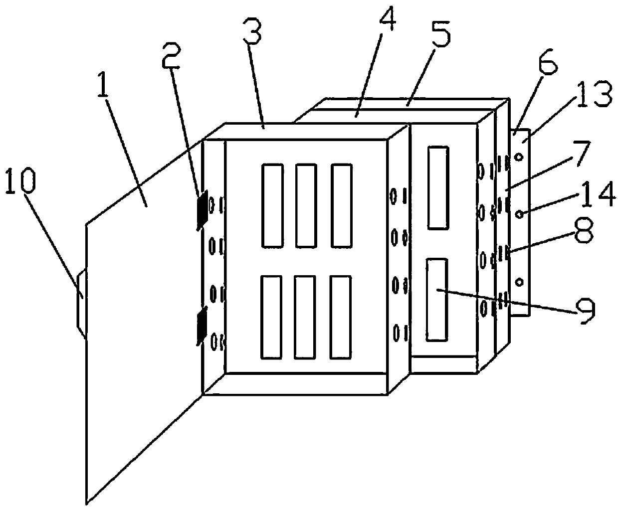
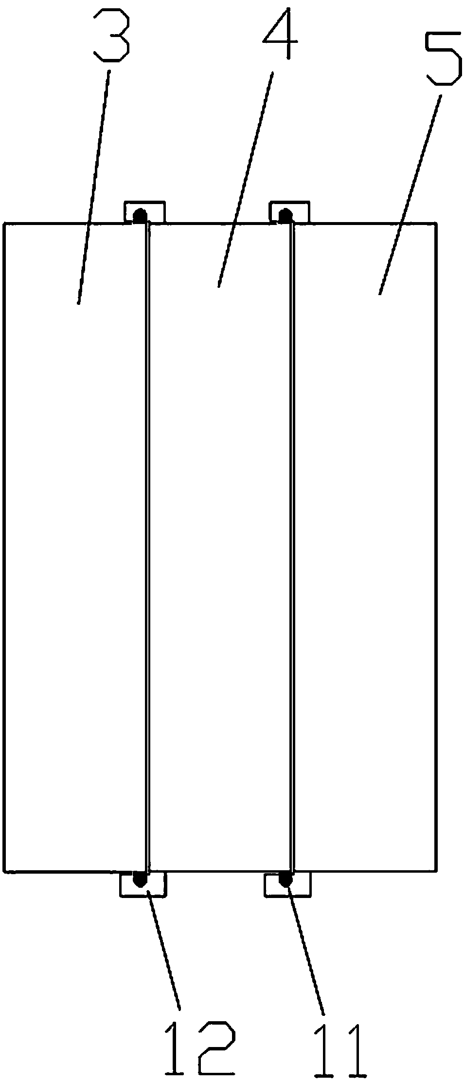
[0016] Figure 1-2 A specific embodiment of the present invention is shown: a multi-layer switch cabinet, including cabinet door 1, hinge 2, switch cabinet A3, switch cabinet B4, switch cabinet C5 and installation flank 6, switch cabinet A3, switch cabinet B4 and switch cabinet C5 are mutually cumulatively arranged, adjacent switch cabinets are slidingly connected, the cabinet door 1 is set on the switch cabinet A3 through the hinge 2, and the installation wings 6 are symmetrically arranged on both sides of the switch cabinet C5, the switch cabinet A3 and the switch cabinet B4 The structure is the same as that of the switch cabinet C5, including the cabinet body 7, the switch mounting plate 8 and the cooling holes 9. The cabinet body 7 is in a square shape. On the side wall of the side, the cabinet door 1 is provided with a rubber insulating handle 10, and the rubber insulating handle 10 is provided at the edge of the outer side of the cabinet door 1, and the installation flan...


PUM


Abstract

The invention discloses a multilayered switch cabinet. The multilayered switch cabinet comprises a cabinet door, a hinge, a switch cabinet A, a switch cabinet B, a switch cabinet C and mounting side wings, wherein the switch cabinet A, the switch cabinet B and the switch cabinet C are mutually stacked; the adjacent switch cabinets are connected in a sliding manner; the cabinet door is arranged onthe switch cabinet A through the hinge; the mounting side wings are symmetrically arranged at two sides of the switch cabinet C; the switch cabinet A, the switch cabinet B and the switch cabinet C have the same structure and each of the switch cabinet A, the switch cabinet B and the switch cabinet C comprises a cabinet body, switch mounting plates and heat dissipation holes, wherein the cabinet body is square, the plurality of switch mounting plates are arranged in the cabinet body and the plurality of heat dissipation holes are formed in side walls at two sides of the cabinet body. Accordingto the multilayered switch cabinet disclosed by the invention, the stacked multilayered switch cabinet can be used for mounting more switches in the same occupied space and the problem that the occupied space of the switch cabinet is large is solved, so that the utilization efficiency of the switch cabinet is extremely improved.

Description

technical field [0001] The invention relates to the field of switch cabinets, in particular to a multi-layer switch cabinet. Background technique [0002] The switch cabinet is used for the transmission and control of electric energy, which can ensure the safety of electric equipment and personnel. The switchgear generates a lot of heat, and at present, only one switchgear can be installed in one area of ​​the switchgear. A large number of lighting needs to install multiple switchgears, which requires a lot of space. [0003] Similar patent CN201420224694.2 The present invention relates to a new type of switchgear, including a switchgear body. The switchgear is divided into upper and lower parts. An empty bag is provided on the top of the upper switchgear and the bottom of the lower switchgear. It is a rectangular parallelepiped structure, the switch cabinet door is provided in the air bag, the slideway is provided in the lower part of the upper switch cabinet air bag, the ...

Claims


Application Information

Patent Timeline
IPC IPC(8): H02B1/30H02B1/38H02B1/56
CPCH02B1/308H02B1/306H02B1/38H02B1/565
Inventor 李培成
Owner 江苏叙然智能科技有限公司
Why Eureka
Try Eureka