
Compressor unit

A compressor and compressed air technology, which is applied to pump devices, measuring devices, mechanical equipment, etc., can solve the problems of open exhaust port, small exhaust port opening area, poor responsiveness, etc.

Inactive Publication Date: 2018-02-13
SUMITOMO RUBBER IND LTD
View PDF1 Cites 0 Cited by
  • Summary
  • Abstract
  • Description
  • Claims
  • Application Information

AI Technical Summary

Problems solved by technology

[0004] However, the opening area of ​​the exhaust port of such a pressure gauge is small, and the exhaust port opens gradually
Therefore, when the compressed air reaches the specified pressure, it is difficult to release the overpressure instantaneously, and the responsiveness is poor, so it is desired to improve the safety accuracy.

Method used


Image

  • Compressor unit
  • Compressor unit
  • Compressor unit

Examples


Embodiment Construction

[0061] Hereinafter, an embodiment of the present invention will be described in detail.

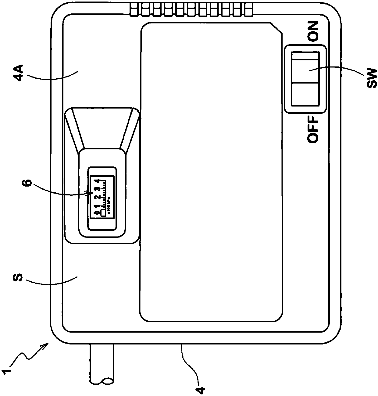
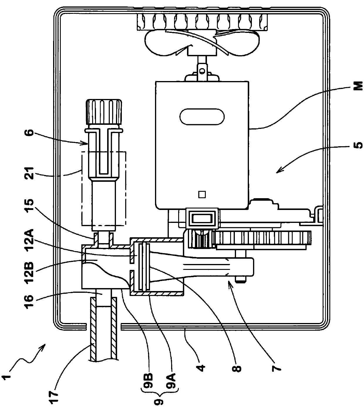
[0062] like figure 1 , 2 As shown, the compressor device 1 includes at least a compressor main body 5 for generating compressed air and a pressure gauge 6 for measuring the pressure of the compressed air in a storage case 4 .

[0063] The compressor main body 5 can appropriately adopt a known structure. The compressor main body 5 of this example includes an electric motor M, a piston 8 connected to the electric motor M via a crank mechanism 7 , and a cylinder 9 for accommodating the piston 8 so as to be capable of reciprocating movement. As the motor M, various DC motors on the market that operate from a 12V DC power supply of an automobile can be used. A power cord provided with a power spark plug connectable to an ignition socket of a car at the tip is connected to the motor M via a power switch SW attached to the upper plate portion 4A of the housing case 4 .

[0064] The cylinder ...


PUM


Abstract

A compressor unit 1 comprises a compressor 5 and a pressure meter 6. The pressure meter 6 comprises: a tubular body 18 communicating with the surge chamber 12B, a meter-piston 19 movable in the tubular body 18 in the longitudinal direction thereof by the compressed air, and a spring 20 biasing the piston 18 toward the front end. The tubular body 18 comprises a small diameter portion 18F in which aseal ring 25 of the piston airtightly contacts with the tubular body, and a large diameter portion 18R in which a gap D is formed between the seal ring and the tubular body. The large diameter portion is connected to the small diameter portion via a step K at which the insider diameter of the tubular body 18 is abruptly changed, whereby when the compressed air reaches to a specified pressure andthe seal ring of the piston is moved beyond the step K, the compressed air is discharged through the gap D.

Description

technical field [0001] The invention relates to a compressor device suitable for a tire blowout repair kit. Background technique [0002] Patent Document 1 below discloses a pressure gauge capable of limiting the supply pressure of compressed air supplied to an air filler (for example, a tire) without providing a safety valve, thereby reducing the size and cost of the compressor device. [0003] This pressure gauge also functions as a safety valve. Specifically, it has: a cylindrical body leading to a buffer chamber of the compressor; a piston movable in the longitudinal direction in the cylindrical body by compressed air from the buffer chamber; and a spring biasing the piston toward the front end. ; and a display unit for displaying the amount of movement of the piston. In addition, an exhaust port is provided on the peripheral wall of the cylindrical body, and when the compressed air reaches a predetermined pressure and the sealing ring of the piston exceeds the exhaust...

Claims


Application Information

Patent Timeline
Patent Type & Authority Applications(China)
IPC IPC(8): F04B41/00F04B39/00G01L17/00B60S5/04
CPCB60S5/04F04B39/00F04B41/00G01L17/00F04B35/06F04B49/24G01L7/163F04B2205/04F04B49/08G01L7/166F04B35/04F04B39/0027
Inventor 河野励
Owner SUMITOMO RUBBER IND LTD
Learn More