A Crankshaft Stress Analysis Method Based on Finite Element

A stress analysis, finite element technology, applied in special data processing applications, instruments, geometric CAD, etc., can solve the problem of low reference value and achieve the effect of crankshaft optimization

Active Publication Date: 2020-06-23
山东云内动力有限责任公司 +1
View PDF9 Cites 0 Cited by
  • Summary
  • Abstract
  • Description
  • Claims
  • Application Information

AI Technical Summary

Problems solved by technology

[0004] In the existing technology, there are few materials based on ANSYS Workbench crankshaft finite element analysis, which is not of high reference value for enterprises that require attention to work efficiency and reliable results, and most mechanical engineers are non-professional software engineers

Method used


Image

  • A Crankshaft Stress Analysis Method Based on Finite Element
  • A Crankshaft Stress Analysis Method Based on Finite Element
  • A Crankshaft Stress Analysis Method Based on Finite Element

Examples


Embodiment Construction

[0036] It should be pointed out that the following detailed description is exemplary and intended to provide further explanation to the present application. Unless defined otherwise, all technical and scientific terms used herein have the same meaning as commonly understood by one of ordinary skill in the art to which this application belongs.

[0037] It should be noted that the terminology used here is only for describing specific implementations, and is not intended to limit the exemplary implementations according to the present application. As used herein, unless the context clearly dictates otherwise, the singular is intended to include the plural, and it should also be understood that when the terms "comprising" and / or "comprising" are used in this specification, they mean There are features, steps, operations, means, components and / or combinations thereof.

[0038] As introduced in the background technology, there is a deficiency in the prior art that the analysis of c...


PUM


Abstract

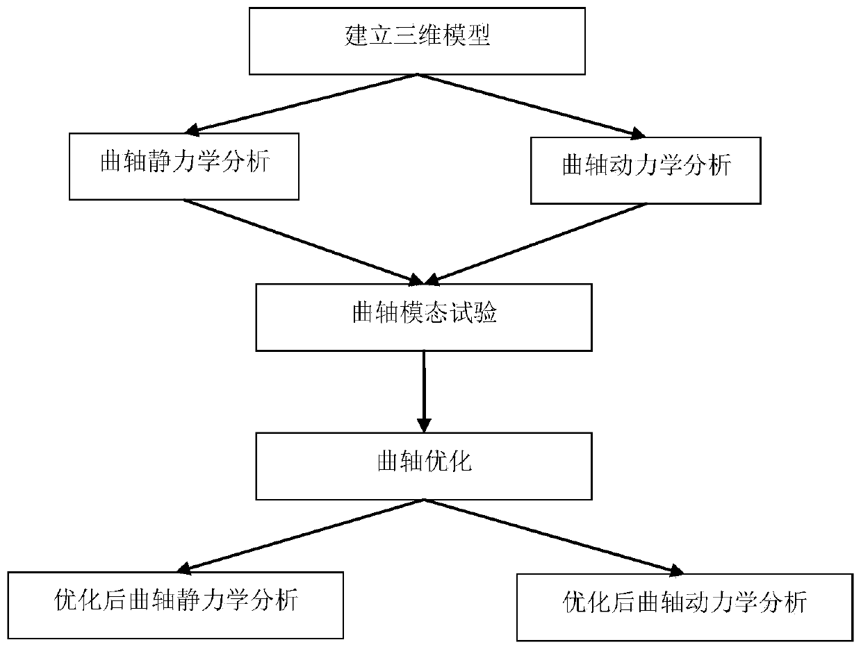
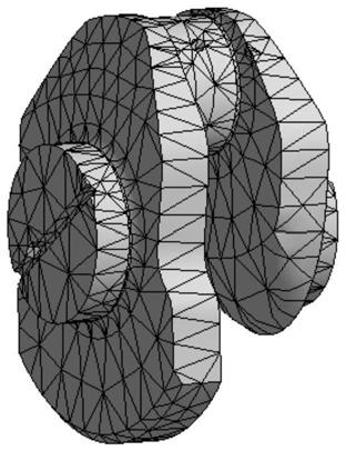
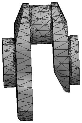
The invention discloses a finite-element-based crankshaft stress analysis method. The problem that in the prior art, analysis of a crankshaft is not suitable for an enterprise is solved. The method has the advantages of being high in practicability, high in accuracy and capable of verifying the fatigue strength of the crankshaft through static analysis. According to the technical scheme, a crankshaft three-dimensional model is established; a crankshaft belt oil hole single-throw model, a crankshaft single-throw simplified model and a crankshaft integral model serve as static analysis models, and static analysis is conducted on the crankshaft; the three models are compared and analyzed, and the optimal model is selected; the crankshaft is subjected to kinetic analysis; a crankshaft modal test is carried out, and an analysis result is checked; the crankshaft is optimized, and post-optimization crankshaft static analysis and kinetic analysis are carried out.

Description

technical field [0001] The invention relates to the field of engines, in particular to a finite element-based crankshaft stress analysis method. Background technique [0002] With the development of modern industrial technology, various new technologies and new research are applied to the design process of the engine, and the emission standards are becoming more and more stringent. The engine is gradually moving towards high speed, high power, low fuel consumption, and low emission. development in a new direction. However, in general, the increase in power will bring many negative effects to the engine. When the power increases, the maximum burst pressure of the piston will increase, which will cause the mechanical load on the diameter of the crankshaft connecting rod to increase, which may cause damage to the crankshaft. . It may also cause the cylinder gas pressure rise rate to be too large, which will cause knocking, increase the combustion noise of the engine, and redu...

Claims


Application Information

Patent Timeline
Patent Type & Authority Patents(China)
IPC IPC(8): G06F30/23G06T17/00G06F119/14
CPCG06F30/15
Inventor 杨永忠李钧袁鸿磊候泉利李长河郑慧珍
Owner 山东云内动力有限责任公司
Why Eureka
Try Eureka