


Quick Research
Generate reliable direction feasibility study reports for your R&D in just a few steps.

Technical Q&A
Discover and master advanced knowledge NOW. Basics, ideas, possibilities, all at once.

Find Solutions
As an expert in R&D theories, this can generate solutions to your technical problems instantly.

Evaluate Feasibility
Analyze your overall solution with one click, know your potential R&D risks in advance.

Monitor Landscape
Get weekly tech updates, stay abreast of the latest tech innovations and key insights.
Thread milling cutter structure
A thread milling cutter and thread technology, which is used in thread cutting tools, metal processing equipment, tangent devices, etc., can solve the problems of easy wear and tear of taps, poor processing quality, and easy vibration of tools, so as to improve processing accuracy and improve Fixed strength, wide range of effects
- Summary
- Abstract
- Description
- Claims
- Application Information
AI Technical Summary
Problems solved by technology
Method used
Image

Examples
Embodiment 1
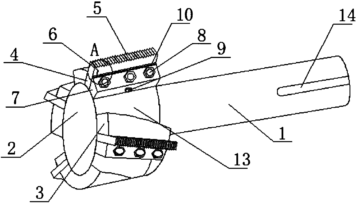
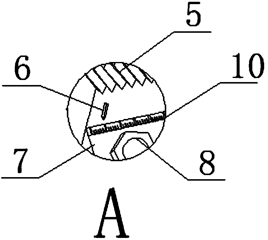
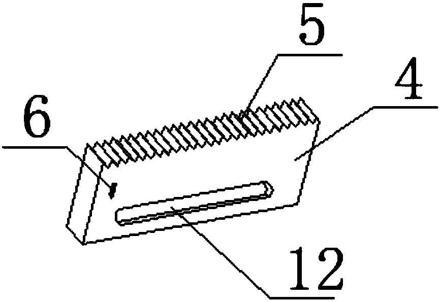
[0023] see figure 1 , image 3 and Figure 4 As shown, a thread milling cutter structure includes a main shaft 1, a rotating body 2, a cutting and milling plate 4 and a cutting and milling thread 5. One end of the main shaft 1 is connected with the rotating body 2, and the rotating body 2 also provides multiple functions while providing power transmission. The installation space of each component, the stopper 3 is set on the rotating body 2, the stopper 3 is that the cutting milling plate 4 is connected, and the other side forms a material guide groove 13 with the fixed block 7, and the cutting milling thread 5 is set on the upper end of the cutting milling plate 4, and the cutting milling plate 4 is provided with a cutting and milling thread 5. The milling thread 5 cuts and mills the material to produce corresponding threads. The milling and milling threads 5 are evenly distributed, and the threads produced by cutting and milling are evenly cut and milled. To indicate, the ...
Embodiment 2
[0025] In addition, refer to Figure 2-Figure 5 , based on the above embodiment, one end of the main shaft 1 is provided with a U-shaped clamping groove 14, which is symmetrically arranged on the main shaft 1, and the clamping groove 14 matches the installation interface, so that the main shaft 1 and the device are installed more firmly , the main shaft 1 will not rotate and slide horizontally when rotating, so as to prevent the thread processing damage caused by the device during processing, the stopper 3 cooperates with the fixed block 7 to form a guide groove 13, and the stopper 3 is uniform on the rotating body 2 Symmetrically distributed, one side of the stopper 3 is a flat surface and the other side is an arc-shaped surface, so that the end face of the stopper 3 is matched with the end face of the cutting milling plate 4, and the two sides of the cutting milling plate 4 are flat surfaces, and the cutting milling plate One side of 4 matches the flat surface of one side of...
PUM
 Abstract
Description
Claims
Application Information
 - R&D Engineer
- R&D Manager
- IP Professional
- Industry Leading Data Capabilities
- Powerful AI technology
- Patent DNA Extraction
Browse by: Latest US Patents, China's latest patents, Technical Efficacy Thesaurus, Application Domain, Technology Topic, Popular Technical Reports.
© 2024 PatSnap. All rights reserved.Legal|Privacy policy|Modern Slavery Act Transparency Statement|Sitemap|About US| Contact US: help@patsnap.com