
On-site defect-eliminating method for acquisition terminal and master station no-communication failures

A technology for collecting terminal and communication faults, applied in wireless communication, measuring devices, instruments, etc., can solve the problems of low collection operation and maintenance efficiency, large on-site operation and maintenance workload, and no terminal and main station.

Active Publication Date: 2018-02-02
STATE GRID ZHEJIANG ELECTRIC POWER +2
View PDF6 Cites 3 Cited by
  • Summary
  • Abstract
  • Description
  • Claims
  • Application Information

AI Technical Summary

Problems solved by technology

[0003] No communication between the acquisition terminal and the main station means that there is no GPRS / CDMA / SMS communication between the operating terminal and the main station for a long time. As a common acquisition operation and maintenance fault, various fault elimination methods are also caused by various fault reasons
Since the number of collection terminals in Zhejiang Province exceeds 3 million, and the manufacturers, batches, protocols, models, accessories, etc. are different, the operation and maintenance teams in each city have different and independent methods for eliminating such faults. Low O&M efficiency and heavy on-site O&M workload

Method used


Image

  • On-site defect-eliminating method for acquisition terminal and master station no-communication failures
  • On-site defect-eliminating method for acquisition terminal and master station no-communication failures
  • On-site defect-eliminating method for acquisition terminal and master station no-communication failures

Examples


Embodiment Construction

[0057] The technical solution of the present invention will be further described in detail below in conjunction with the accompanying drawings.

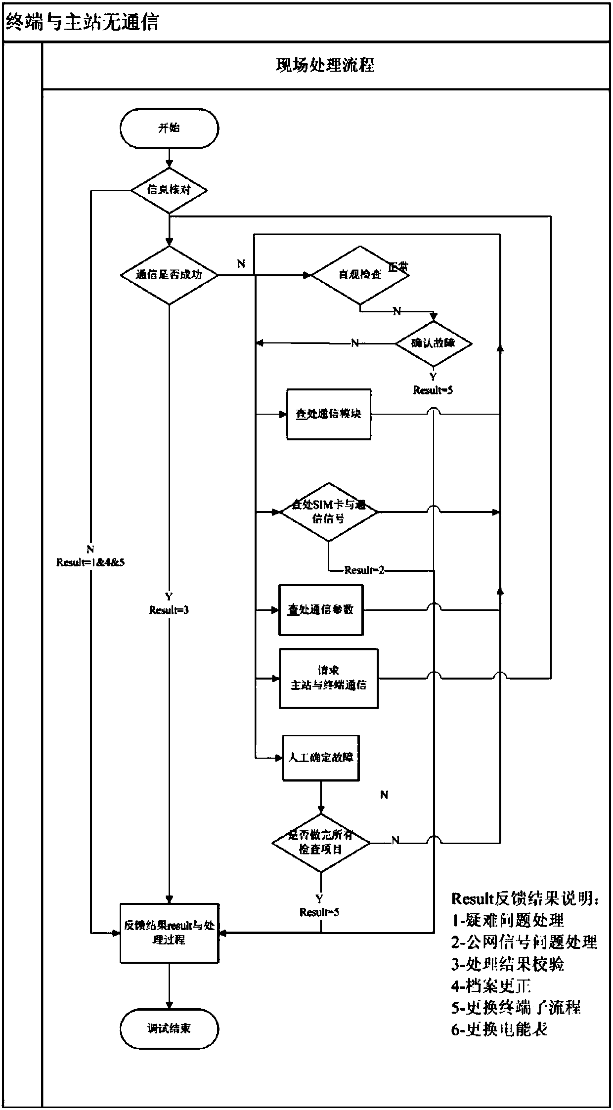
[0058] Such as figure 1 Shown, the present invention comprises the following steps:

[0059] 1) Information check: the collection operation and maintenance personnel check whether the on-site information is consistent with the system information, including checking the account number, terminal asset number, and electric energy meter asset number;

[0060] 2) Carry out various related inspections of the equipment according to the optimized sequence, including visual inspection, investigation of communication modules, investigation of SIM cards and communication signals, investigation of communication parameters, and determination of fault causes. The optimal sequence is based on historical fault records and fault logic of relevant inspection items Analyze and arrange relevant algorithms in order of priority;

[0061] 3) Carry out co...


PUM


Abstract

The invention relates to an on-site defect-eliminating method, in particular to on-site defect-eliminating method for acquisition terminal and master station no-communication failures. At present, operation and maintenance teams in various cities have different and independent on-site defect-eliminating methods, the acquisition operation and maintenance efficiency is low, and the on-site operationand maintenance workload is great. The on-site defect-eliminating method comprises the steps of: checking information; performing various relevant inspection on equipment according to an optimizationsequence; performing corresponding defect elimination according to the found failures; verifying a defect-eliminating result; confirming the failure manually; and recording feedback results in the processing process. The on-site defect-eliminating method combines the system flow of the current acquisition operation and maintenance defect-eliminating process, performs on-site defect elimination byadopting the systematic professional defect-eliminating method which is convenient in use, optimized and efficient according to various failure causes of no-communication between the acquisition terminal and the master station, achieves the effects of improving the acquisition operation and maintenance efficiency, reducing on-site operation and maintenance workload and enhancing professionalization of the acquisition operation and maintenance teams, further guarantees the meter-reading rate of an electricity utilization information acquisition system, and supports the work development of state grid marketing.

Description

technical field [0001] The invention relates to an on-site defect elimination method, in particular to an on-site defect elimination method without communication failure between a collection terminal and a master station. Background technique [0002] The current operation and maintenance work lacks systematic, continuous, forward-looking and professional operation and maintenance teams. With the continuous development of operation and maintenance work, the conditions for systematic professional collection and operation and maintenance through experience summarization and technical means are already available. [0003] No communication between the acquisition terminal and the main station means that there is no GPRS / CDMA / SMS communication between the operating terminal and the main station for a long time. As a common acquisition operation and maintenance fault, various fault elimination methods are also caused by various fault reasons. Since the number of collection termina...

Claims


Application Information

Patent Timeline
IPC IPC(8): G01D21/02H04W24/04
CPCG01D21/02H04W24/04
Inventor 郏正济谢烽杨宁郑斌王伟峰丁峰尤子龙陈友勇江婷
Owner STATE GRID ZHEJIANG ELECTRIC POWER
Learn More