
A mechanical limit mechanism and limit method for increasing motion stroke

A technology of limit mechanism and motion stroke, applied in the direction of mechanical equipment, brake type, etc., can solve the problem of not being able to realize the limit requirements of two extreme positions, and achieve the effect of simple structure and motion form, wide application range, and simplified installation.

Active Publication Date: 2019-05-10
BEIJING INST OF RADIO METROLOGY & MEASUREMENT
View PDF6 Cites 0 Cited by
  • Summary
  • Abstract
  • Description
  • Claims
  • Application Information

AI Technical Summary

Problems solved by technology

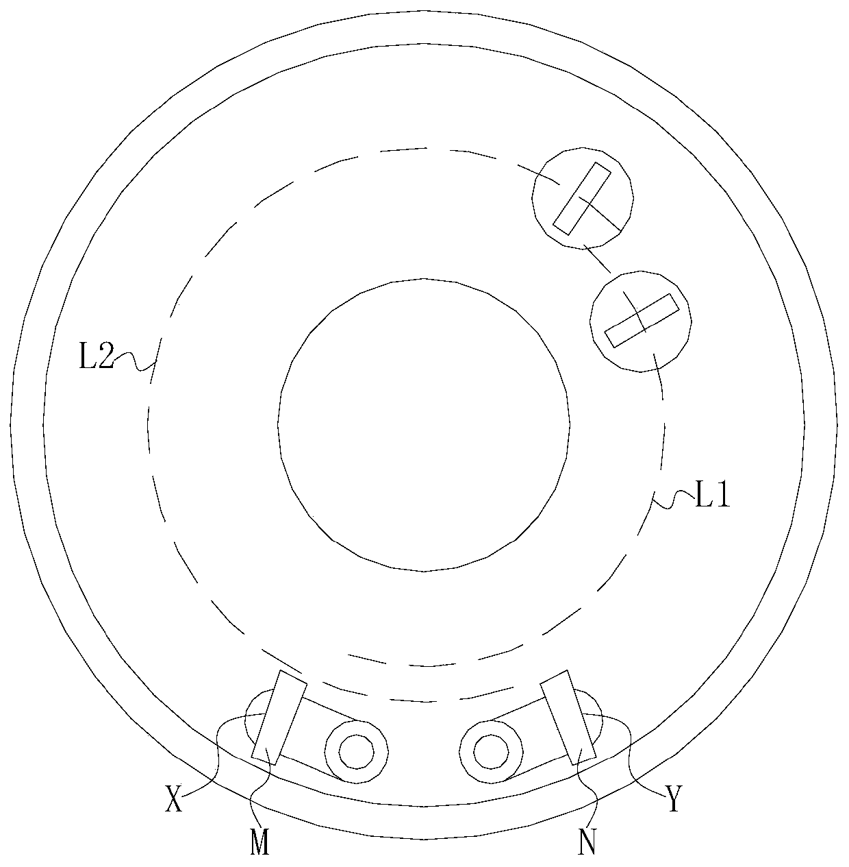
If the limit position X is just on L2 (or the limit position Y is just on L1), the moving parts will interfere with the limit bumper during the movement, and the two fixed limit bumpers cannot be realized by the traditional method of two fixed limit bumpers. The limit demand of limit position

Method used


Image

  • A mechanical limit mechanism and limit method for increasing motion stroke
  • A mechanical limit mechanism and limit method for increasing motion stroke
  • A mechanical limit mechanism and limit method for increasing motion stroke

Examples


Embodiment Construction

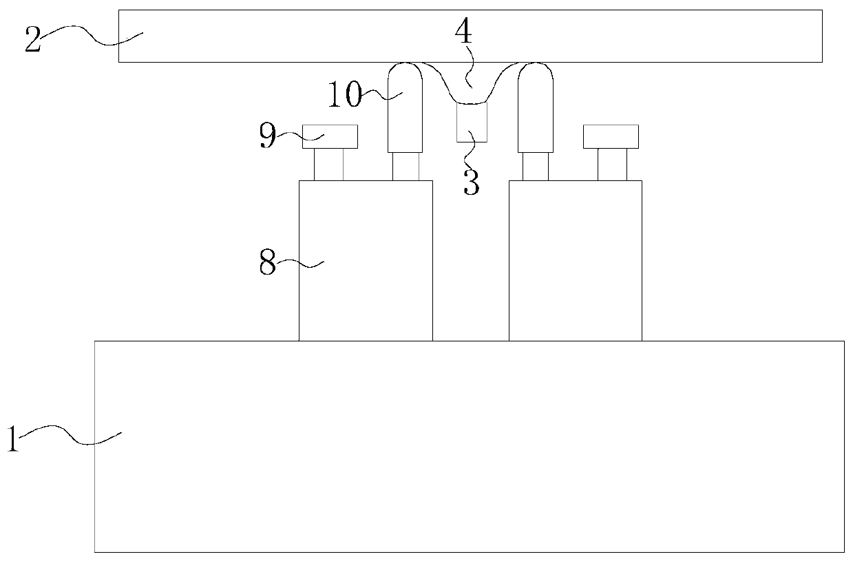
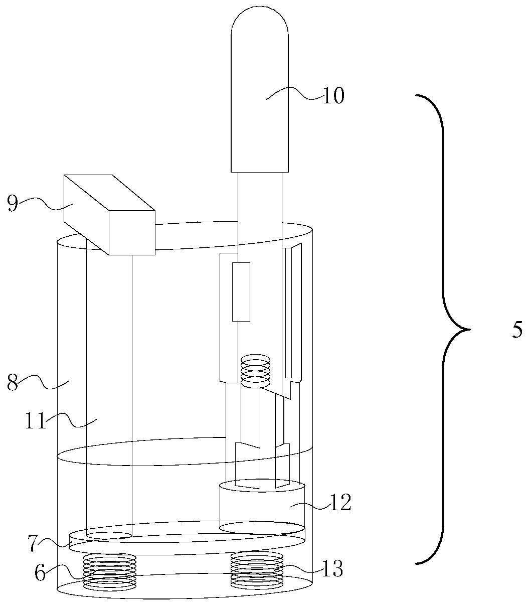
[0023] Such as Figure 2-3 As shown, a mechanical limit mechanism for increasing the movement stroke includes a moving part 2, and the bottom end of the moving part 2 is respectively provided with a cylindrical or cuboid moving bumper 3, and arc-shaped bumpers with arcuate surfaces on both sides. 4. The lower end of the moving bumper 3 is lower than the lower end of the arc-shaped bumper 4; the moving part 2 has two arc-shaped or two linear-shaped motion trajectories L1, L2, and there is an interference area between L1 and L2. A fixed bracket 1 is arranged below the fixed bracket 1, and two fixed bumper parts 5 are arranged on the fixed bracket 1 and in the area where L1 and L2 interfere, and the two fixed bumper parts 5 are arranged symmetrically with respect to the center line of the interference area between L1 and L2;

[0024] The fixed bumper part 5 includes a vertically arranged housing 8 with an oblong cross-section, the bottom of the inner cavity of the housing 8, and ...


PUM


Abstract

The invention particularly relates to a mechanical limiting mechanism and method for increasing the movement stroke, and the mechanical limiting mechanism and method are wide in application range. Anarc-faced bumping block and a movement bumping block move under driving of a movement component, blocking bumping blocks are all in a descending state originally, and the arc-faced bumping block is firstly in contact with a slide rod of a first fixed bumping block component, so that the blocking bumping block of the first fixed bumping block component rises up; then, the arc-faced bumping block isin contact with a slide rod of a second fixed bumping block component, and the blocking bumping block of the second fixed bumping block component rises up; the movement bumping block and the blockingbumping block of the second fixed bumping block component are limited, the movement component retreats from a limiting area after conducting reverse movement to make contact with the slide rods of the two fixed bumping block components, so that the two blocking bumping blocks restore to be in the descending state, and limiting is achieved by limiting the movement of the movement component throughascending and descending of the blocking bumping blocks; and the movement range of the movement component can be intervened mutually without being influenced, and the application range is wide.

Description

technical field [0001] The invention relates to the technical field of mechanical limit, in particular to a mechanical limit mechanism and a limit method for different limit positions in multiple moving directions of a motion mechanism. Background technique [0002] Due to the demand for functionality and safety of electromechanical products, a limit mechanism is often set at a specific position of the electromechanical product to limit the range of motion of the motion mechanism to achieve a certain function, or to prevent the motion mechanism from falling out of the set range of motion to ensure the product or operator safety. [0003] The traditional limit mechanism often adopts the form of two collision blocks, that is, install a collision block relatively fixed to the fixed part on the fixed part, and install a collision block relatively fixed to the moving part at the corresponding position on the moving part. When the moving part moves to the set limit position, the ...

Claims


Application Information

Patent Timeline
Patent Type & Authority Patents(China)
IPC IPC(8): F16D71/00
CPCF16D71/00
Inventor 王鲲飞吴翔何鑫
Owner BEIJING INST OF RADIO METROLOGY & MEASUREMENT
Learn More