Tool for accurately measuring axis position of pipe
A measuring tube and axis technology, which is applied to measuring devices, mechanical measuring devices, and mechanical devices, etc., can solve the problems of poor measurement accuracy, large errors, and difficulty in finding marking points, and achieve high-precision installation, strong practicability, and high efficiency. The effect of installation
- Summary
- Abstract
- Description
- Claims
- Application Information
AI Technical Summary
Problems solved by technology
Method used
Image

Examples
Embodiment 1
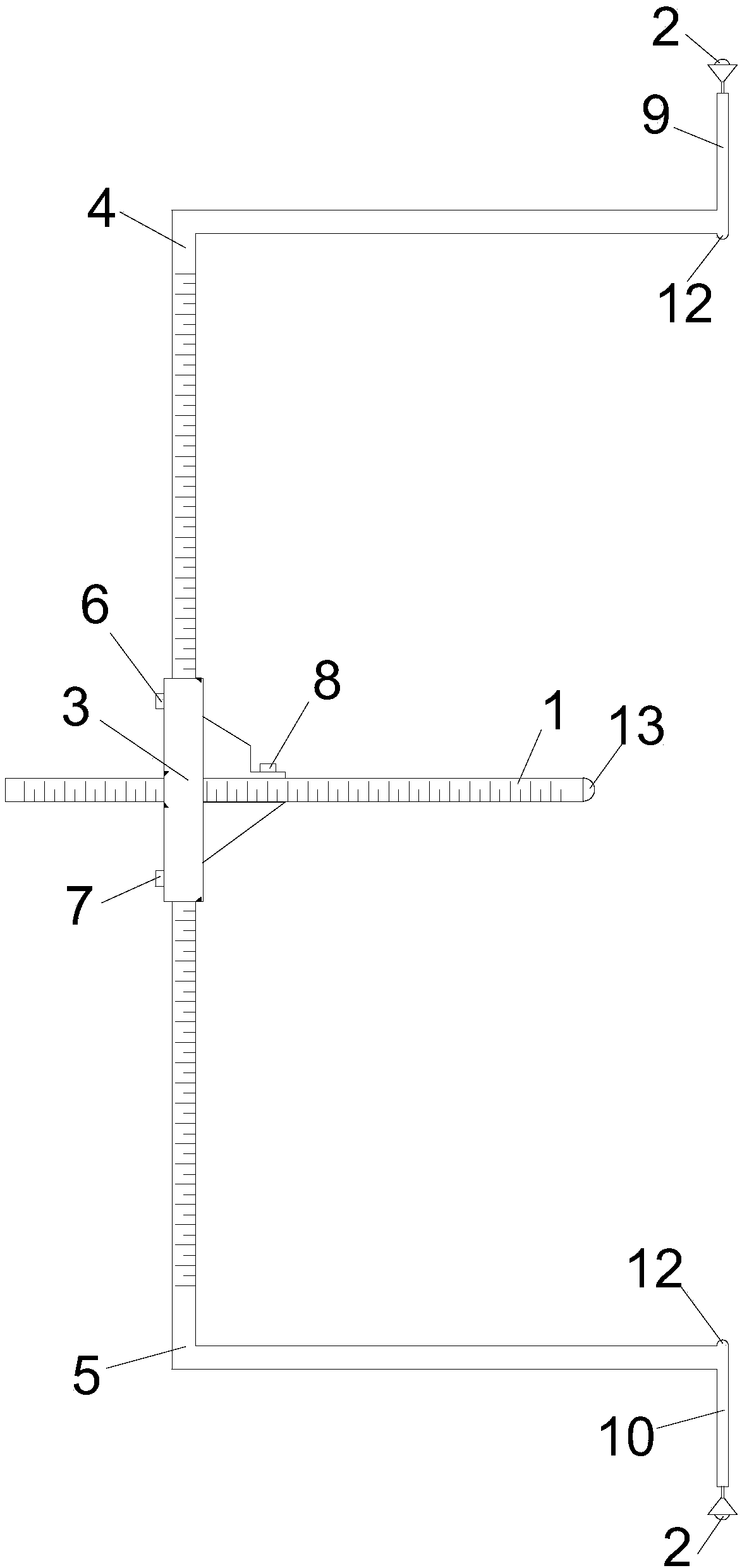
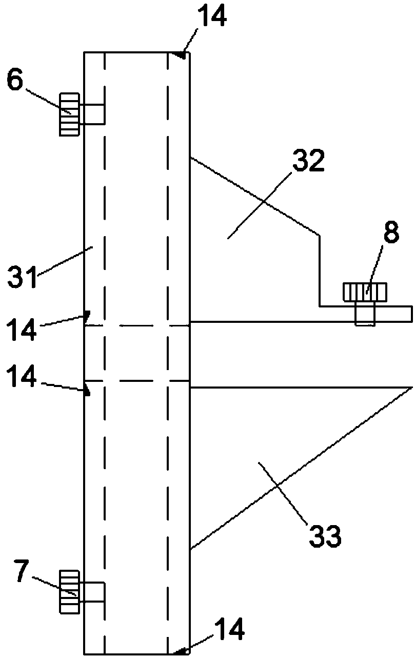
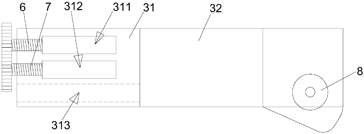
[0033]In this embodiment, a tool for accurately measuring the position of the pipe axis includes a ruler 1, a target body 2, a marking block 3, an upper L-shaped ruler 4 and a lower L-shaped ruler 5, and the above-mentioned marking blocks 3 are arranged in sequence from front to back There are a first vertical through groove 311 , a second vertical through groove 312 and a transverse through groove 313 . like figure 1 As shown, the above-mentioned L-shaped ruler 4 is limited to include vertical sections and horizontal sections perpendicular to each other, and the above-mentioned lower L-shaped ruler 5 is defined to also include vertical sections and horizontal sections perpendicular to each other, and the above-mentioned upper L-shaped ruler 4 and the lower section are defined. The horizontal section of the L-shaped chi 5 is all towards the right, that is, the vertical section of the above-mentioned upper L-shaped chi 4 and the lower L-shaped chi 5 is connected to the left end...
Embodiment 2
[0044] This embodiment is further improved on the basis of Embodiment 1. In this embodiment, as figure 1 Shown, limit on the upper surface of the right end of the horizontal section of the above-mentioned L-shaped chi 4 is provided with a vertically upward upper connecting rod 9, a prism (that is, the target body 2) is installed on this On the upper end of the upper connecting rod 9, a lower connecting rod 10 vertically downwards is provided on the lower surface of the right end of the horizontal section of the above-mentioned lower L-shaped ruler 5, and another prism (that is, the target body 2) is installed by another rotation Frame 15 is installed in the lower end of this lower connecting rod 10, and the length that limits above-mentioned upper connecting rod 9 and lower connecting rod 10 is identical, can guarantee like this the identical distance of the center of two prisms with respect to the central position of the present invention, thereby makes measurement obtain The...
Embodiment 3
[0046] This embodiment is further limited on the basis of Embodiment 2. In this embodiment, it is defined that the upper connecting rod 9 and the lower connecting rod 10 are all telescopic rods, so that it is convenient for the user to adjust the two target bodies 2 according to the needs of the present invention. The distance between the center positions enhances the utility of the invention.
[0047] As a specific implementation of this embodiment, in this embodiment, such as Figure 5 and Image 6 As shown, the above-mentioned upper connecting rod 9 is defined to include an upper outer tube 91 and an upper inner tube 92 that are adapted to each other. The upper inner tube 92 is sleeved in the upper outer tube 91 and the upper inner tube 92 can be placed on the upper Outer tube 91 is free to slide up and down telescopically, and the lower end of above-mentioned upper outer tube 91 is installed on the upper surface of the right end of the horizontal section of above-mentione...
PUM
 Abstract
Description
Claims
Application Information
 - R&D
- Intellectual Property
- Life Sciences
- Materials
- Tech Scout
- Unparalleled Data Quality
- Higher Quality Content
- 60% Fewer Hallucinations
Browse by: Latest US Patents, China's latest patents, Technical Efficacy Thesaurus, Application Domain, Technology Topic, Popular Technical Reports.
© 2025 PatSnap. All rights reserved.Legal|Privacy policy|Modern Slavery Act Transparency Statement|Sitemap|About US| Contact US: help@patsnap.com