
Multi-bead embroidery device

A bead embroidery and bead embroidery technology, applied in auxiliary devices, embroidery machines, embroidery machine mechanisms, etc., can solve the problems of embroidery bead hole offset, inconvenient use, easy rotation of embroidery beads, etc. The effect of sending beads

Active Publication Date: 2018-01-30
朱月眉
View PDF6 Cites 8 Cited by
  • Summary
  • Abstract
  • Description
  • Claims
  • Application Information

AI Technical Summary

Problems solved by technology

At present, embroidery machines include equipment that can only embroider beads of one specification and color and equipment that can embroider beads of two specifications and colors at the same time. During the use of equipment that can embroider beads of two specifications and colors at the same time, usually two specifications and colors Beads will fall into the bead holder at the same time. During the beading process, there will be too many beads or few beads, and the beads cannot be fed continuously and accurately, which will affect the embroidery quality. The bead holder is moved by the bead feeding mechanism to make the correct specifications and colors The embroidery beads fall into the jaws of the clamp of the bead feeding mechanism, and the moving direction of the bead lowering seat is perpendicular to the moving direction of the pulley. Beads are prone to rotation, which makes the bead hole of the embroidered bead shift, so it is difficult to ensure that the bead hole of the embroidered bead and the embroidery needle are precisely matched to cause injection. When there are more than two color specifications, the structure of the equipment will be complicated and inconvenient to use.

Method used


Image

  • Multi-bead embroidery device
  • Multi-bead embroidery device
  • Multi-bead embroidery device

Examples


Embodiment Construction

[0026] It should be noted that the features in the various embodiments of the present invention may be combined with each other in the absence of explicit limitation or conflict. The present invention will be described in detail below with reference to the accompanying drawings and examples.

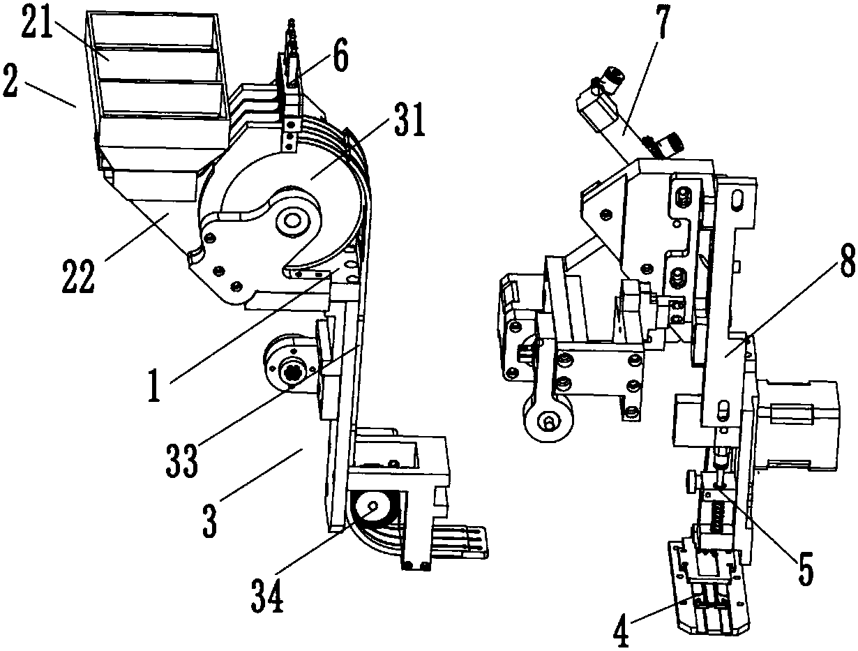
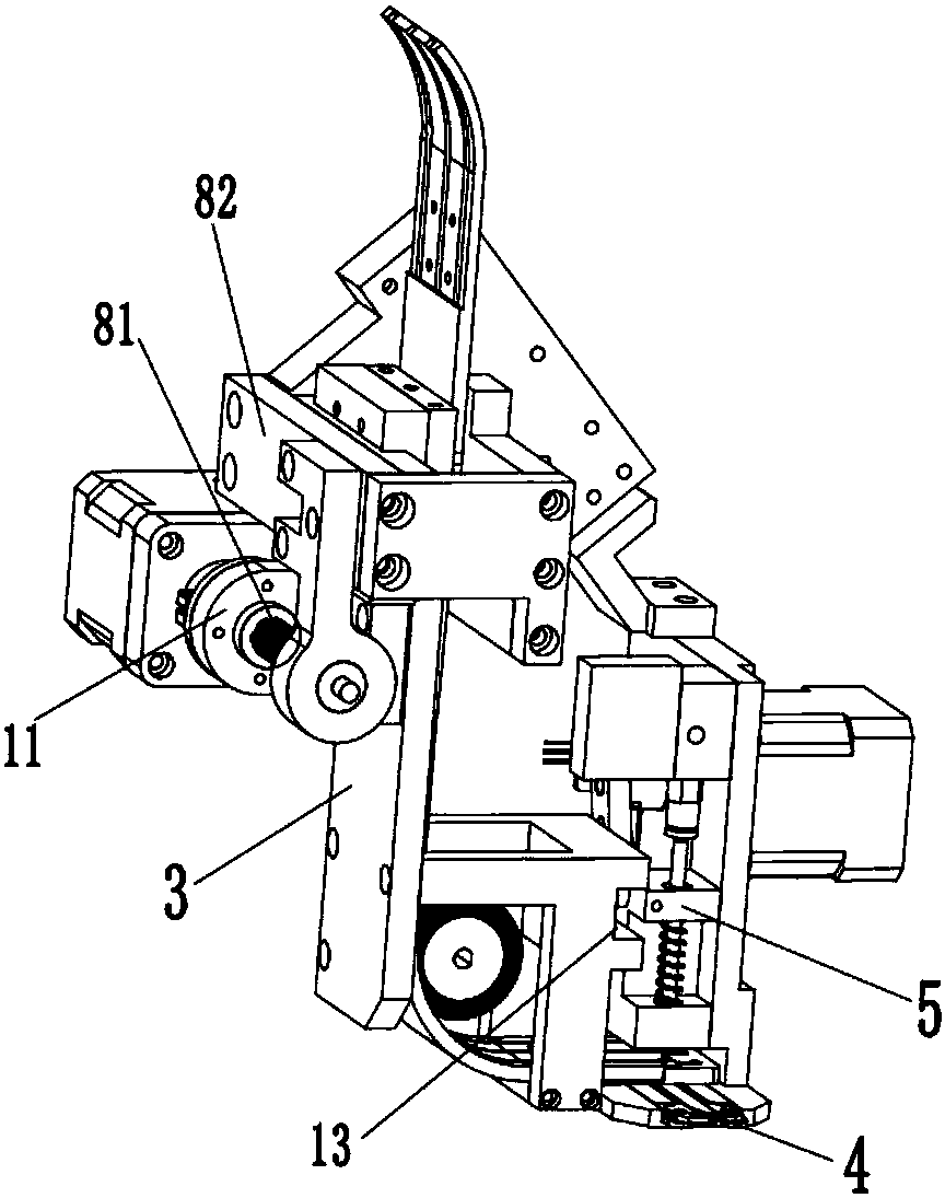
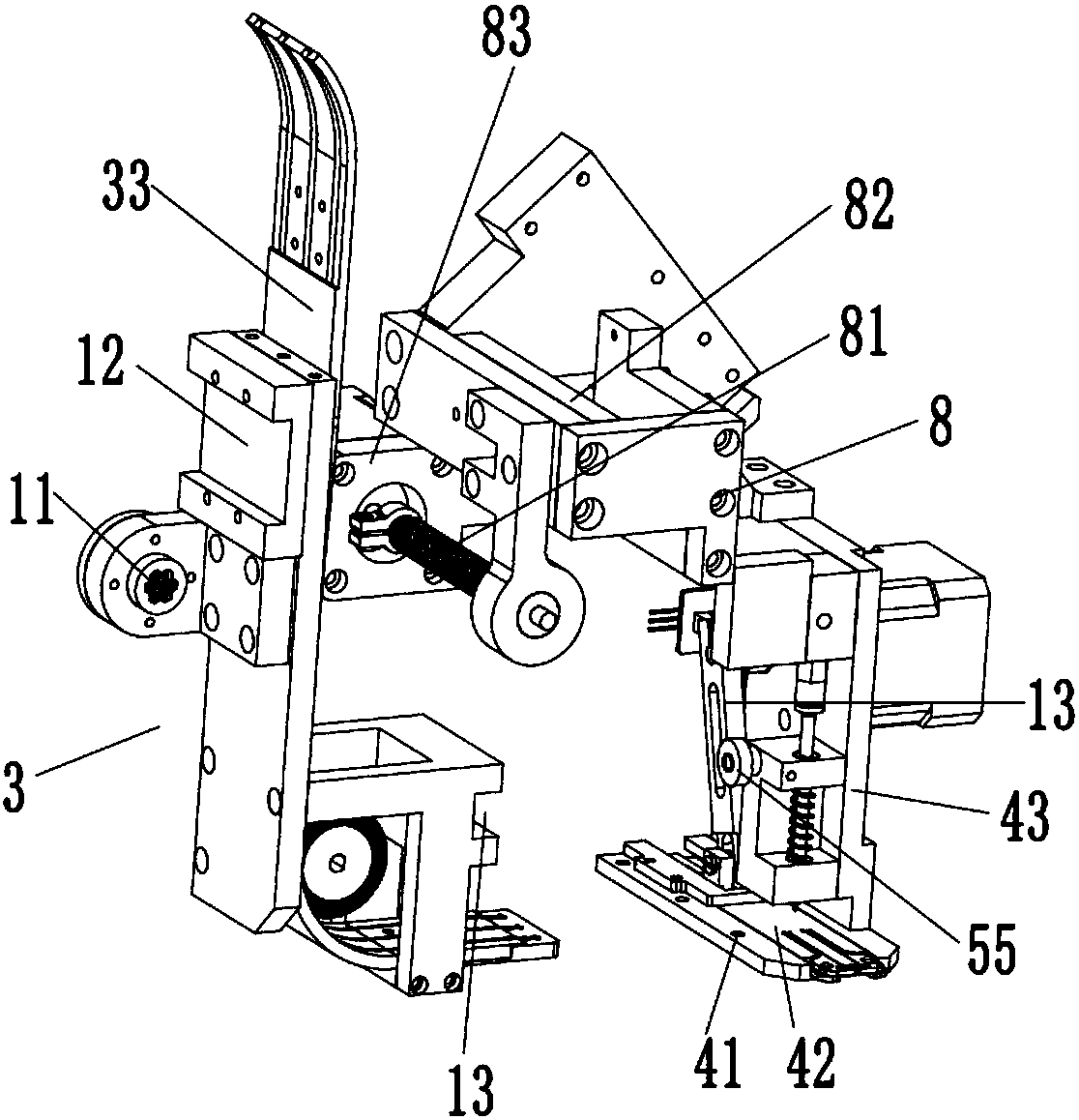
[0027] refer to Figure 1 to Figure 8 ,like figure 1 and figure 2 The shown multi-bead embroidery device includes a first frame 1, a second frame 8, a hopper 2, an automatic bead-feeding mechanism 3, a bead-feeding mechanism 4 and a bead-washing mechanism 5, and the first frame 1 It is movably arranged on the second frame 8, the hopper 2 and the automatic bead lowering mechanism 3 are sequentially arranged on the first frame 1, and the bead feeding mechanism 4 and the bead flushing mechanism 5 are both It is arranged on the second frame 8, wherein the hopper 2 includes a total hopper 21 and a lower hopper 22, the lower hopper 22 is connected to the discharge port of the total hopper ...


PUM


Abstract

The invention discloses a multi-bead embroidery device. The device comprises a first rack, a second rack, a hopper, an automatic bead unloading mechanism, a bead delivery mechanism and a bead dashingmechanism, the first rack is connected with a second rack in a movable arrangement way, the hopper and the automatic bead unloading mechanism are arranged on the first rack in sequence, the bead delivery mechanism and the bead dashing mechanism are arranged on the second rack, at least two material unloading grooves are arranged in the hopper, the automatic bead unloading mechanism comprises a material unloading guide rail and at least two material delivery wheels, the material delivery wheel delivering an embroidered bead located in the corresponding material unloading groove into a corresponding elastic clamp located on the material unloading guide rail, the first rack is moved to enable the corresponding elastic clamp move to the bead dashing mechanism, and the embroidered bead locatedin the corresponding elastic clamp is dashed into a clamping mouth of the bead delivery mechanism to complete bead unloading and realize bead exchanging under the action of the bead dashing mechanism.The multi-bead embroidery device has the advantages that continuous, accurate delivery of variety of colors of embroidered beads can be met, and accurate bead embroidery can be ensured.

Description

technical field [0001] The invention relates to the technical field of bead embroidery equipment, in particular to a multi-bead embroidery device. Background technique [0002] Embroidering various patterns on clothes can add a lot of color to people's dress. Usually, beads are embroidered on the fabric, which can achieve a better three-dimensional decorative effect. At present, embroidery machines include equipment that can only embroider beads of one specification and color and equipment that can embroider beads of two specifications and colors at the same time. During the use of equipment that can embroider beads of two specifications and colors at the same time, usually two specifications and colors Beads will fall into the bead holder at the same time. During the beading process, there will be too many beads or few beads, and the beads cannot be fed continuously and accurately, which will affect the embroidery quality. The bead holder is moved by the bead feeding mechan...

Claims


Application Information

Patent Timeline
IPC IPC(8): D05C7/08D05C13/00
Inventor 朱月眉
Owner 朱月眉
Learn More