Substrate treatment apparatus

A substrate processing device and technology for substrates, which are applied in electrical components, semiconductor/solid-state device manufacturing, circuits, etc., can solve the problems of large-scale cleaning nozzles, prolonged cleaning time, and reduced cleaning time.

Inactive Publication Date: 2018-01-19
DAINIPPON SCREEN MTG CO LTD
View PDF11 Cites 2 Cited by
  • Summary
  • Abstract
  • Description
  • Claims
  • Application Information

AI Technical Summary

Problems solved by technology

However, in the cleaning nozzle of Document 2, the number of droplets ejected from a predetermined range per unit time is significantly smaller than that of the two-fluid nozzle.
Therefore, in order to perform the same treatment as the two-fluid nozzle, it is necessary to increase the size of the cleaning nozzle, prolong the cleaning time, etc.

Method used


Image

  • Substrate treatment apparatus
  • Substrate treatment apparatus
  • Substrate treatment apparatus

Examples


Embodiment Construction

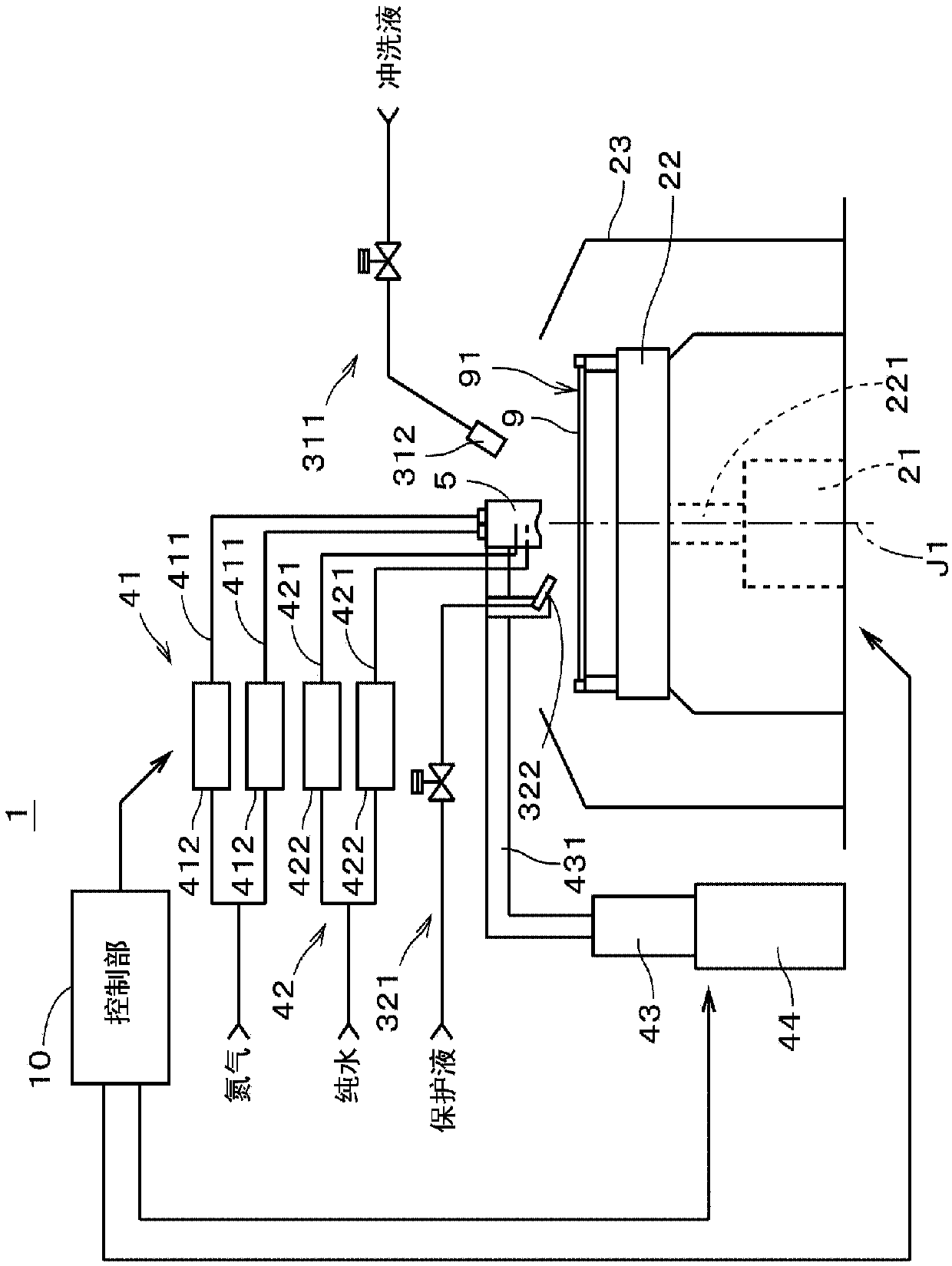
[0037] figure 1 It is a figure which shows the structure of the substrate processing apparatus 1 which concerns on 1st Embodiment of this invention. Each component in the substrate processing apparatus 1 is controlled by the control unit 10 . The substrate processing apparatus 1 includes a spin jig 22 as a substrate holding unit, a spin motor 21 as a substrate rotation mechanism, and a cover 23 surrounding the spin jig 22 . The substrate 9 is placed on the rotary jig 22 . The rotary jig 22 clamps the substrate 9 by bringing a plurality of pinching members into contact with the peripheral edge of the substrate 9 . As a result, the substrate 9 is held in a horizontal posture by the rotating jig 22 . In the following description, main surface 91 of substrate 9 facing upward is referred to as "upper surface 91". Fine patterns are formed on the upper surface 91 .

[0038] A shaft 221 extending in the vertical direction (vertical direction) is connected to the lower surface of ...


PUM


Abstract

A substrate treatment apparatus is provided with: a substrate rotating mechanism that rotates a substrate; a nozzle section that jets droplets of a treatment liquid toward a main surface of the substrate; and a nozzle moving mechanism that moves the nozzle section in the direction along the main surface. The nozzle section is provided with two guide surfaces (511), two gas jetting ports (512), andtwo treatment liquid supply ports (513). Through the gas jetting ports, a gas is jetted along the guide surfaces, and gas flows are formed along the guide surfaces. The treatment liquid supply portsare provided in the guide surfaces, and through each of the treatment liquid supply ports, the treatment liquid is supplied between each of the gas flows and each of the guide surfaces. In the nozzlesection, when one of the two gas jetting ports is considered as a first gas jetting port which forms a gas flow that carries, as a thin film flow, the treatment liquid to a lower end edge (516) of theguide surfaces, the other gas jetting port is considered as a second gas jetting port that forms a gas flow that collides with the treatment liquid scattered from the lower end edge. Consequently, the substrate can be suitably treated by jetting a plurality of droplets having a uniform diameter.

Description

technical field [0001] The present invention relates to a substrate processing device. Background technique [0002] Conventionally, in a manufacturing process of a semiconductor substrate (hereinafter, simply referred to as a "substrate"), a substrate processing apparatus for supplying droplets of a processing liquid onto a substrate surface has been used. For example, a so-called external mixing type two-fluid nozzle is installed in a substrate processing apparatus disclosed in JP 2004-349501 A (Document 1). At one end of the two-fluid nozzle, an annular gas discharge port opens, and the liquid discharge port opens near the center of the gas discharge port. Since the pure water ejected from the liquid ejection port travels almost straight, the nitrogen gas ejected from the annular gas ejection port advances toward the converging point outside the housing in a converging manner, so the nitrogen gas and the pure water collide and mix at the converging point, thereby A jet ...

Claims


Application Information

Patent Timeline
Patent Type & Authority Applications(China)
IPC IPC(8): H01L21/304
CPCH01L21/67051H01L21/67017H01L21/6715B08B3/022B08B3/024B08B5/023H01L21/68764
Inventor 波多野章人林豊秀桥本光治小林健司高桥弘明
Owner DAINIPPON SCREEN MTG CO LTD
Why Eureka
Try Eureka