
Image carrier unit and image forming device with image carrier unit

A technology of image carrier and main body, which is applied in the direction of electrical recording technology using charge graphics, equipment and instruments using electrical recording technology using charge graphics, and can solve image unevenness, conduction resistance fluctuations, and uneven residual charges on the surface of photosensitive drums. Equalization problem, to achieve the effect of suppressing image unevenness and stabilizing conductivity

Active Publication Date: 2021-03-05
KYOCERA DOCUMENT SOLUTIONS INC
View PDF9 Cites 0 Cited by
  • Summary
  • Abstract
  • Description
  • Claims
  • Application Information

AI Technical Summary

Problems solved by technology

However, the oil seeps to the sliding surface of the sintered bearing to form an insulating oil film, which will hinder the conduction
In addition, there is a risk that the conduction resistance may fluctuate due to the amount of oil impregnated into the sintered bearing or the load applied to the bearing.
When the on-resistance of the photosensitive drum fluctuates, there is a problem of unevenness in the residual charge on the surface of the photosensitive drum, resulting in uneven images

Method used


Image

  • Image carrier unit and image forming device with image carrier unit
  • Image carrier unit and image forming device with image carrier unit
  • Image carrier unit and image forming device with image carrier unit

Examples


Embodiment Construction

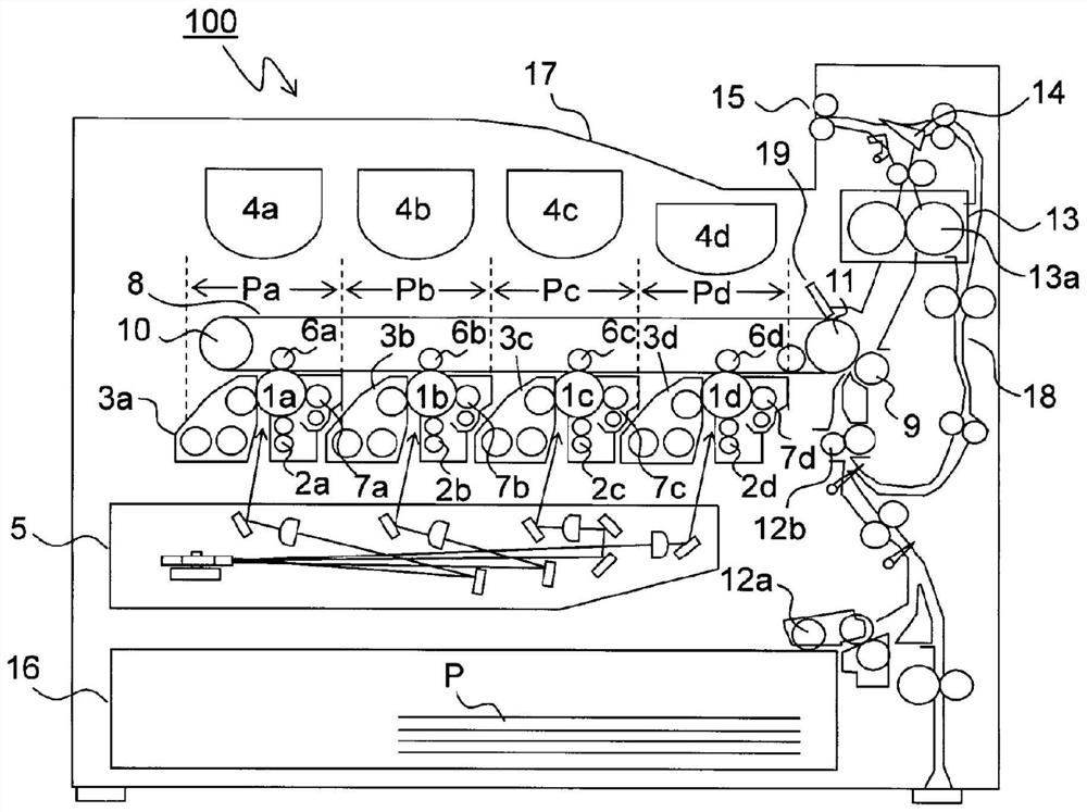
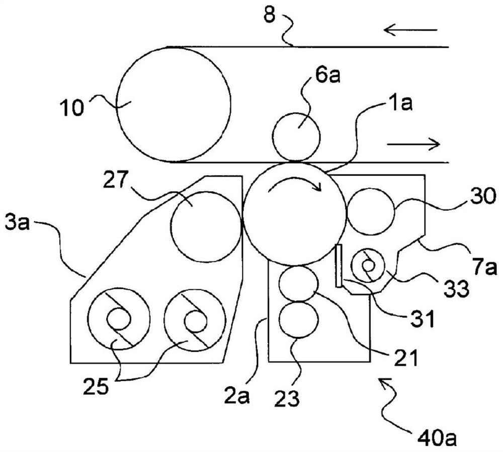
[0022] Hereinafter, embodiments of the present invention will be described with reference to the drawings. figure 1 It is a cross-sectional view showing a schematic configuration of an image forming apparatus 100 according to an embodiment of the present invention, and a tandem color printer is shown here. The four image forming sections Pa, Pb, Pc, and Pd are viewed from the upstream side in the conveyance direction ( figure 1 middle left) are sequentially arranged in the main body of the image forming apparatus 100 . The above-mentioned image forming parts Pa to Pd are provided correspondingly to images of different four colors (cyan, magenta, yellow and black), and sequentially form images of cyan, magenta, yellow and black through the processes of charging, exposure, development and transfer, respectively. image.

[0023] Photosensitive drums 1 a to 1 d carrying visible images (toner images) of respective colors are arranged in the image forming sections Pa to Pd. Moreo...


PUM


Abstract

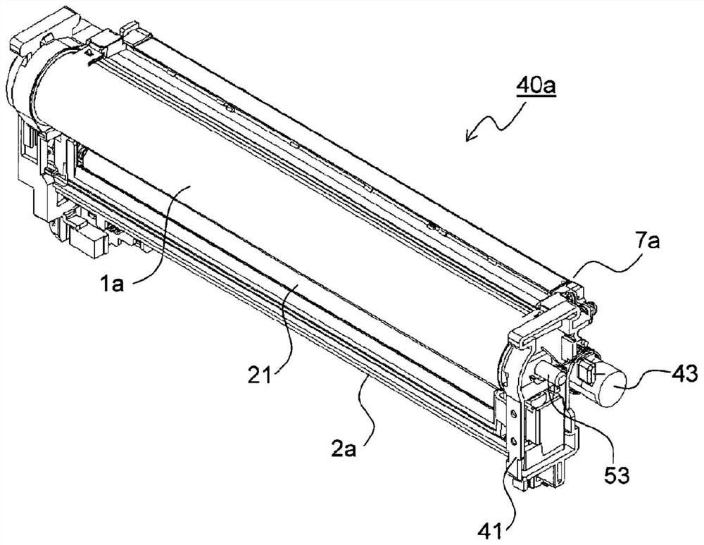
The image carrier unit (40a-40d) provided by the present invention is provided with an image carrier (1a-1d) and a unit casing (41). The image carriers (1a-1d) comprise: an image carrier body (50) with a photosensitive layer formed on the outer peripheral surface; a through hole (51a) is fixed on both ends of the image carrier body (50) and formed in the rotation center of the image carrier body (50). ) of the flange part (51); the cylindrical sintered oil-impregnated bearing (55) fixed in the through hole (51a) of the flange part (51); the sintered oil-impregnated bearing (55) and the image carrier body (50) ) an electrically conductive conducting member (57); a support shaft (53) slidably passing through the sintered oil-impregnated bearing (55) and fixed to the unit housing (41); and a contact spring (60) having a support shaft (53) ) inserted coil spring portion (60a) is sandwiched in a compressed state between the axial end face of the sintered oil-impregnated bearing (55) and the unit housing (41), so that the sintered oil-impregnated bearing (55) and the support shaft (53) ) is electrically connected.

Description

technical field [0001] The present invention relates to image forming apparatuses such as copiers, printers, and facsimiles, and more particularly, to an image carrier unit carrying an electrostatic latent image and an image forming apparatus including the image carrier unit. Background technique [0002] In a conventional image forming apparatus employing electrophotography, an electrostatic latent image is formed on a uniformly charged photosensitive drum (image carrier), the electrostatic latent image is developed into a toner image and an image is formed on paper (recording medium) . [0003] Sintered bearings are provided at both ends of the photosensitive drum, and when the photosensitive drum is assembled on the unit frame, the sintered bearings are in contact with the electrode chips provided on the unit frame. The electrode chip is formed of a sintered body, and is connected to the main body of the image forming apparatus via a ground wire or the like. In this way...

Claims


Application Information

Patent Timeline
Patent Type & Authority Patents(China)
IPC IPC(8): G03G21/16G03G15/00
CPCG03G15/751G03G21/1652
Inventor 森下浩树花野劝
Owner KYOCERA DOCUMENT SOLUTIONS INC
Learn More