
Method for calculating existing shield tunnel displacements caused by new under-crossing tunnels

A technology for shield tunneling and displacement calculation, which is applied in calculation, special data processing applications, instruments, etc., and can solve problems such as inability to calculate segment misalignment, bolt failure, and impact on subway safety

Inactive Publication Date: 2018-01-19
ZHEJIANG UNIV CITY COLLEGE
View PDF1 Cites 12 Cited by
  • Summary
  • Abstract
  • Description
  • Claims
  • Application Information

AI Technical Summary

Problems solved by technology

[0002] When a new tunnel passes through the lower part of the existing shield tunnel, the original force balance is broken, causing the redistribution of stress in the existing shield tunnel, resulting in excessive lateral or longitudinal deformation, causing segment cracking, joint opening, Bolt failure and other phenomena affect the safety of the subway
Existing calculation methods to analyze the existing shield tunnel under the new tunnel are based on the elastic foundation beam method, which simplifies the shield tunnel into a homogeneous elastic beam, does not consider the "joint effect" between the tunnel rings, and cannot calculate the segment displacement The amount differs from the actual

Method used


Image

  • Method for calculating existing shield tunnel displacements caused by new under-crossing tunnels
  • Method for calculating existing shield tunnel displacements caused by new under-crossing tunnels
  • Method for calculating existing shield tunnel displacements caused by new under-crossing tunnels

Examples


Embodiment Construction

[0078] The present invention will be further described below in conjunction with the examples. The description of the following examples is provided only to aid the understanding of the present invention. It should be pointed out that for those skilled in the art, without departing from the principles of the present invention, some improvements and modifications can be made to the present invention, and these improvements and modifications also fall within the protection scope of the claims of the present invention.

[0079] This patent uses the "shear staggered platform model" to equate the tunnel to short elastic foundation beams connected by shear springs, and uses the principle of minimum potential energy to calculate the longitudinal deformation of the existing shield tunnel when the new tunnel passes under, and The amount of staggering between adjacent tunnel rings and the magnitude of the shear force between the rings can evaluate the structural safety and impermeabilit...


PUM


Abstract

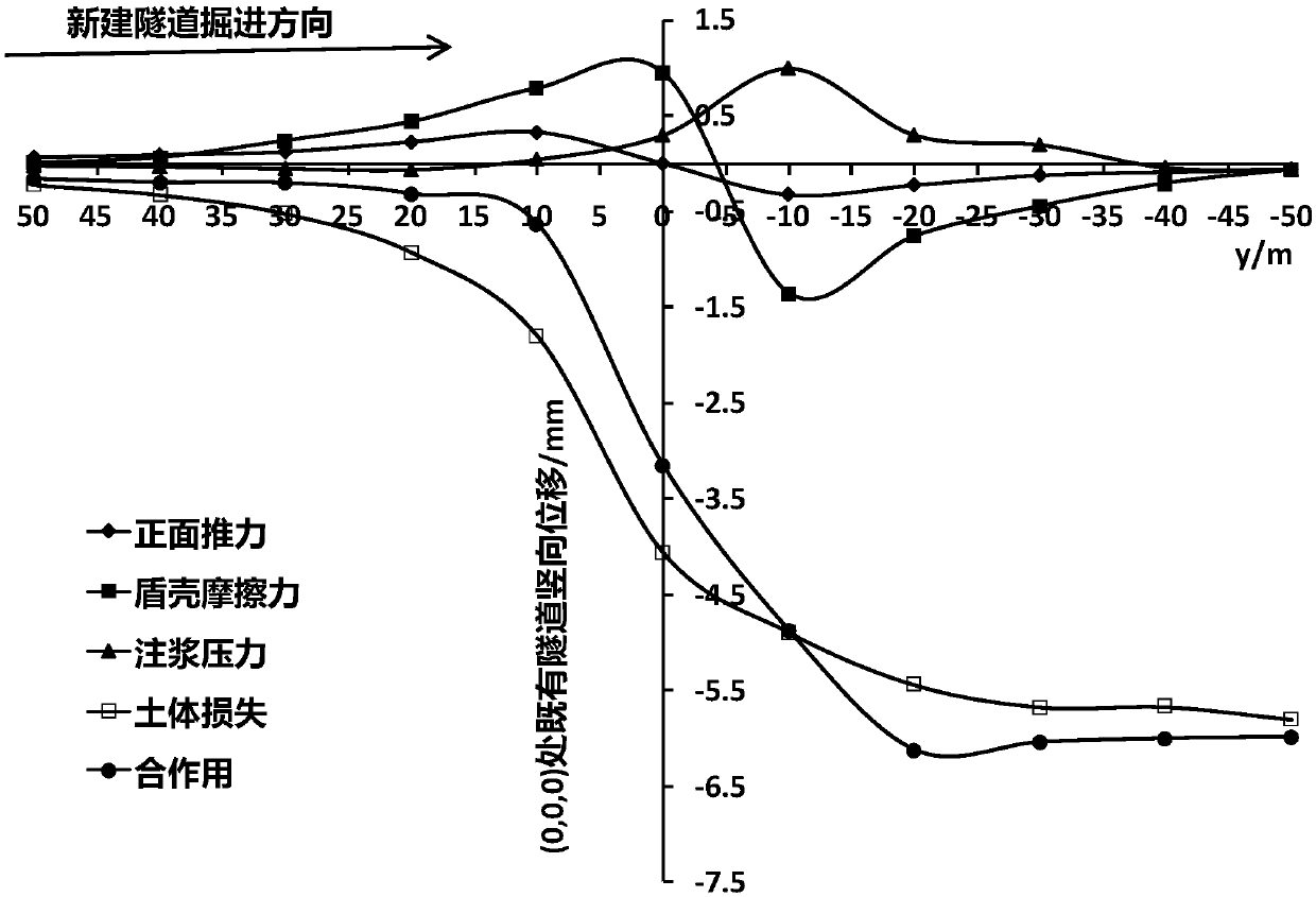
The invention relates to a method for calculating existing shield tunnel displacements caused by new under-crossing tunnels. The method comprises the following steps of: 1, calculating existing tunneladditional stresses caused by a new under-crossing tunnel: a vertical additional stress <sigma>z-q generated by cutter head additional thrust q, a vertical additional stress <sigma>z-f generated by shield shell friction force f, vertical additional stresses <sigma>z-p1 and <sigma>z-p2 generated by slip casting additional pressure p and an additional stress generated by soil mass loss; and 2, calculating longitudinal deformation of the tunnel on the basis of a principle of minimum potential energy: total potential energy of a shield tunnel, a displacement function of an assumed tunnel lining ring and a variation control equation. The method has the beneficial effects that joint effect among tunnel rings is considered, structural characteristics and physical characteristics of tunnels are sufficiently considered, and longitudinal displacements, caused by new under-crossing tunnels, of existing shield tunnels can be rapidly calculated by utilizing Matlab, so that safety of existing tunnel structures under the action of the new under-crossing tunnels can be judged and relatively accord with practical stress and deformation of the shield tunnels.

Description

technical field [0001] The invention relates to a calculation method for calculating the displacement of an existing shield tunnel caused by the underpass of a new tunnel, belonging to the technical field of underground engineering. Background technique [0002] When a new tunnel passes through the lower part of the existing shield tunnel, the original force balance is broken, causing the redistribution of stress in the existing shield tunnel, resulting in excessive lateral or longitudinal deformation, causing segment cracking, joint opening, Bolt failure and other phenomena affect the safety of the subway. Existing calculation methods to analyze the existing shield tunnel under the new tunnel are all based on the elastic foundation beam method, which simplifies the shield tunnel into a homogeneous elastic beam, does not consider the "joint effect" between the tunnel rings, and cannot calculate the segment displacement The amount is different from the actual one. Contents...

Claims


Application Information

Patent Timeline
Patent Type & Authority Applications(China)
IPC IPC(8): G06F17/50
Inventor 魏纲俞国骅杨波朱田宇陆世杰崔程虹张鑫海王新
Owner ZHEJIANG UNIV CITY COLLEGE
Learn More