Steel wire rope bending device and method thereof
A technology of steel wire rope and elbow, applied in the field of steel wire rope processing, can solve the problems of inconvenient operation of steel wire rope elbow, and achieve the effects of improved safety factor, strong portability, and convenient and quick operation.
- Summary
- Abstract
- Description
- Claims
- Application Information
AI Technical Summary
Problems solved by technology
Method used
Image

Examples
Embodiment 1
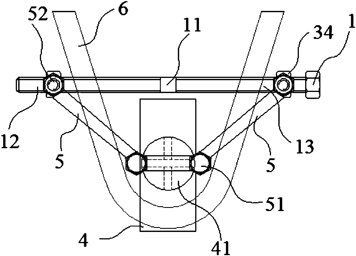
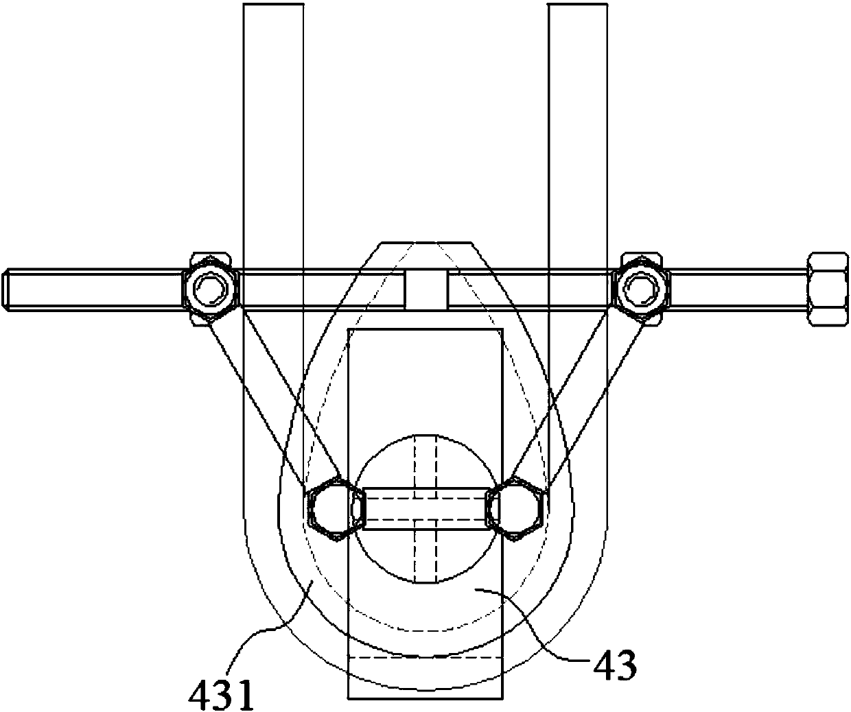
[0044] combined with Figure 1-3 , a wire rope elbow device in this embodiment includes a screw rod 1, a follower rod 5, a support plate 4, a support shaft 41 and a clamping portion 34, wherein the support plate 4 is provided with a support shaft 41, and the support plate 4 is provided with a support shaft 41. They are respectively movably connected with one end of the two follower rods 5, and the other ends of the two follower rods 5 are movably connected with a clamping part 34. The parts 34 are respectively located on the screw rod 1 and cooperate with the corresponding reverse thread part 12 and positive thread part 13 .
[0045] Rotate the screw rod 1 so that the two clamping parts 34 on the reverse threaded part 12 and the positive threaded part 13 run away from each other. To facilitate the wire rope to lean against the support shaft 41, the two ends of the wire rope directly cross the upper parts of the two follower rods 5, put them on the screw rod 1 between the two ...
Embodiment 2
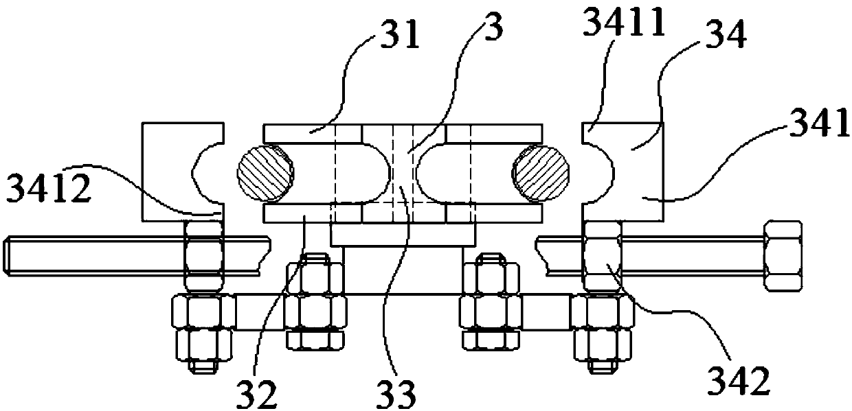
[0048] combined with figure 1 , 2 And 3, a kind of wire rope elbow device of the present embodiment, compared with embodiment 1, the two sides of the screw rod middle part 11 on the described screw rod 1 are reverse thread part 12 and positive thread part 13 respectively, and described screw rod middle part 11 is provided with a compensation clamping part 3, the compensation clamping part 3 cooperates with the clamping part 34, and the compensation clamping part 3 cooperates with the clamping part 34 to clamp the end of the steel wire rope 6 together to facilitate the assembly of the elbow Holder.
Embodiment 3
[0050] combined with figure 1 , 2 And 3, a kind of wire rope elbow device of the present embodiment, compared with embodiment 1 or 2, described compensation clamping part 3 comprises upper end plate 31, lower end plate 32 and connecting part 33, the upper end of connecting part 33 and The upper end plate 31 is connected, the lower end of the connecting portion 33 is connected with the lower end plate 32 , and the radius of the arc groove formed between the upper end plate 31 and the lower end plate 32 is smaller than the radius of the steel wire rope 6 .
[0051] The radius of the arc-shaped groove formed between the upper end plate 31 and the lower end plate 32 is less than the radius of the steel wire rope 6, that is, the arc length of the arc-shaped groove is less than the semicircle length of the cross-section of the steel wire rope 6. After the elbow is formed, the end of the steel wire rope 6 is convenient from The arc groove is taken out.
PUM
 Abstract
Description
Claims
Application Information
 - R&D
- Intellectual Property
- Life Sciences
- Materials
- Tech Scout
- Unparalleled Data Quality
- Higher Quality Content
- 60% Fewer Hallucinations
Browse by: Latest US Patents, China's latest patents, Technical Efficacy Thesaurus, Application Domain, Technology Topic, Popular Technical Reports.
© 2025 PatSnap. All rights reserved.Legal|Privacy policy|Modern Slavery Act Transparency Statement|Sitemap|About US| Contact US: help@patsnap.com