
Motor end cover pushing feeding device used for motor end cover and bearing automatic press fitting device

A technology of motor end caps and press-fitting devices, which is applied in the directions of electromechanical devices, electric components, and manufacturing of motor generators, can solve the problems of troublesome feeding of motor end caps and troublesome manual operation.

Pending Publication Date: 2018-01-16
ZHEJIANG LINIX MOTOR
View PDF7 Cites 7 Cited by
  • Summary
  • Abstract
  • Description
  • Claims
  • Application Information

AI Technical Summary

Problems solved by technology

[0002] In the assembly of the motor, the bearing and the end cover of the motor need to be press-fitted. At present, the assembly worker usually performs the press-fitting of the bearing and the end cover through the press-fitting tool. The feeding, loading and unloading of the motor end cover, manual operation will be very troublesome
[0003] Among them, one end of the end cover of some motors is formed with a boss of the bearing chamber protruding axially outward, and the other end of the end cover of the motor is provided with at least two positioning posts for matching with the casing, and the positioning posts are relatively located in the bearing chamber. On the outside of the boss, if the motor end caps are stacked up and down, the lower motor end cap will cause a radial limit to the adjacent upper motor end cap, and the assembler needs to remove the upper motor end cap Raise and then move the motor end cover, or fix the motor end cover on the second upper layer, so that the bottom motor end cover is lowered and then moved, the feeding of the motor end cover is very troublesome

Method used


Image

  • Motor end cover pushing feeding device used for motor end cover and bearing automatic press fitting device
  • Motor end cover pushing feeding device used for motor end cover and bearing automatic press fitting device
  • Motor end cover pushing feeding device used for motor end cover and bearing automatic press fitting device

Examples


Embodiment Construction

[0022] The present invention will be further described below according to the accompanying drawings and specific embodiments.

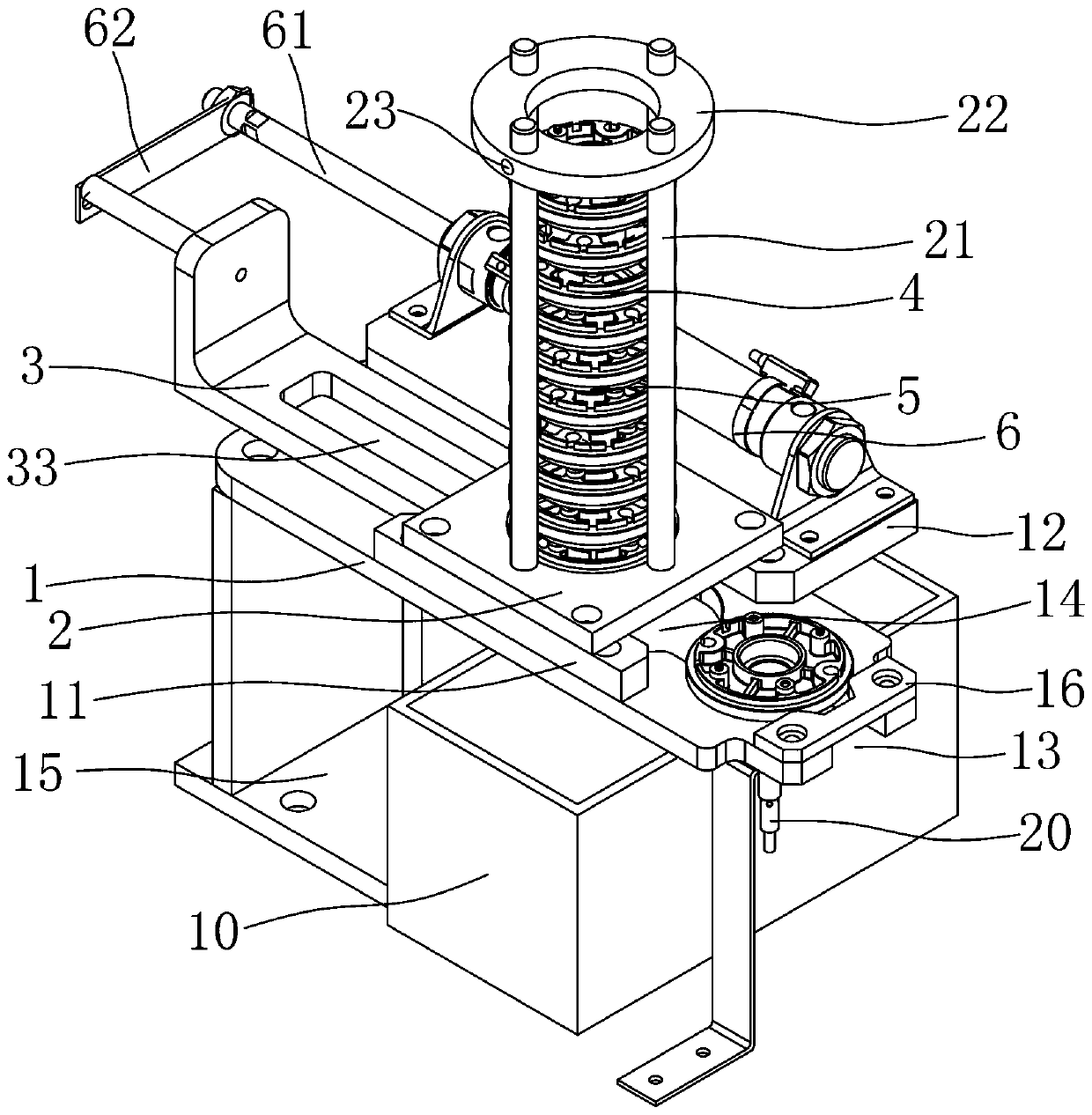
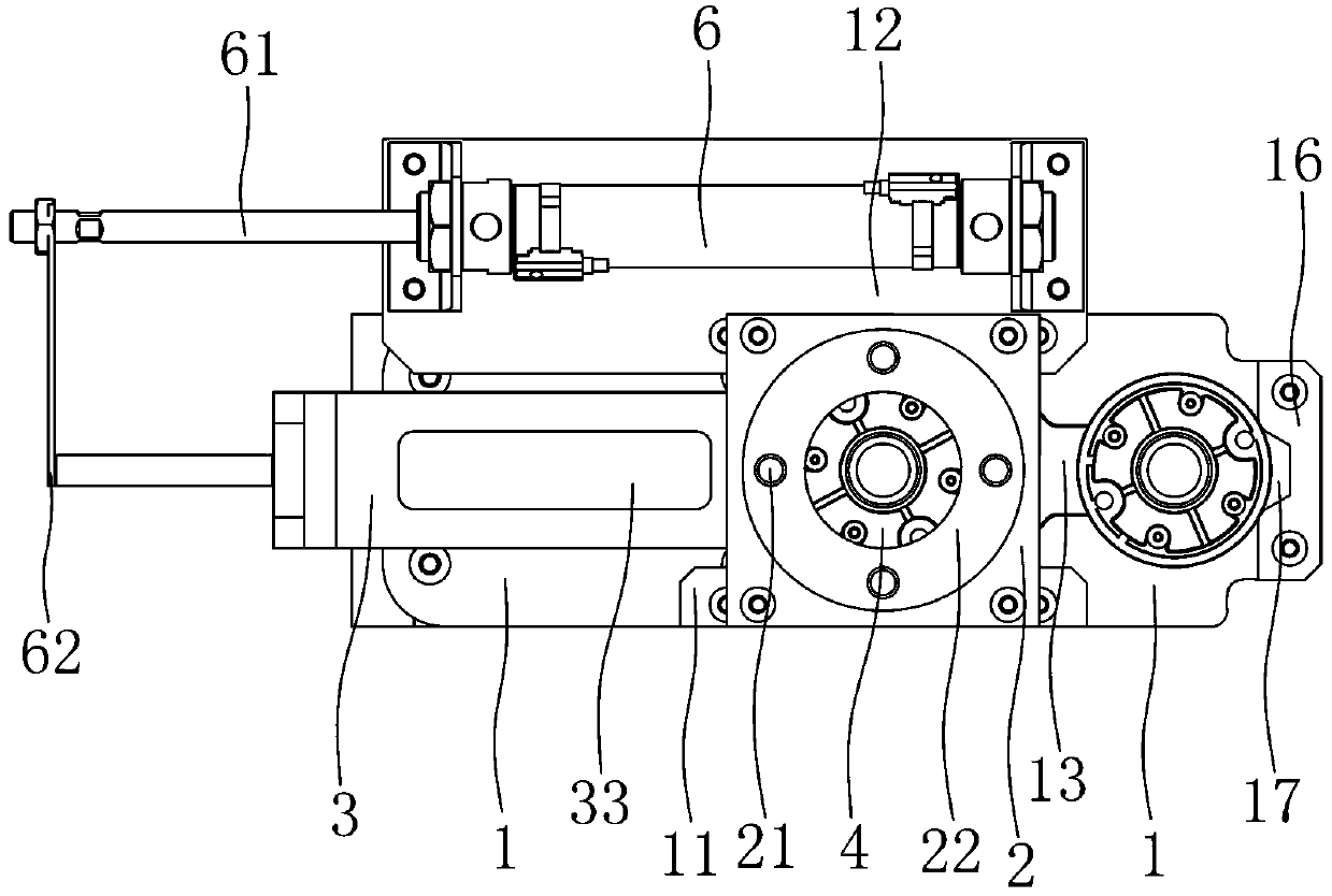
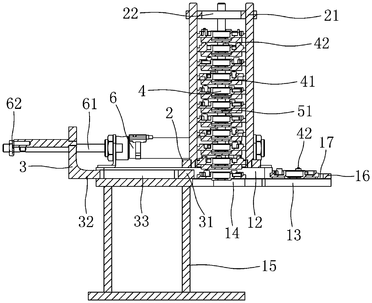
[0023] Depend on figure 1 , figure 2 As shown, a motor end cover push feeding device for an automatic press-fitting device for a motor end cover and a bearing includes a fixed plate 1, a guide plate 2 and a push block 3, and a left limit block 11 and a right limit block are fixed on the fixed plate 1. Position block 12, guide plate 2 is located on the upper side of left limit block 11 and right limit block 12, and guide plate 2 is formed with an accommodating groove that penetrates up and down for placing the motor end cover. The accommodating groove is circular, and the left limit block The right wall of 11 is relatively located on the left side of the receiving groove, the left wall of the right limiting block 12 is relatively located on the right side of the receiving groove, and the pushing block 3 is located between the left limiting block 11 a...


PUM


Abstract

The invention discloses a motor end cover pushing feeding device used for a motor end cover and bearing automatic press fitting device. The motor end cover pushing feeding device comprises a fixing plate, a guiding plate and a pushing block. A left limiting block and a right limiting block are fixed to the fixing plate, the guiding plate is located on the upper side of the left limiting block andthe upper side of the right limiting block, a containing groove used for containing motor end covers is formed in the guiding plate in a vertical penetration mode, the right wall of the left limitingblock is relatively located on the left side of the containing groove, the left wall of the right limiting block is relatively located on the right side of the containing groove, the pushing block islocated between the left limiting block and the right limiting block, the motor end covers are arranged in a vertically overlapped mode, a cushioning block is arranged between every two adjacent motorend covers, a falling groove is formed in the fixing plate, the cushioning blocks fall into the lower side of the fixing plate through the falling groove, and the upper end faces of the cushioning blocks are concaved to form receding grooves for achieving receding for bearing housing bosses of the motor end covers. The motor end cover pushing feeding device has the advantage that the stacked motor end covers can be pushed in a separated mode for feeding without manual operation.

Description

technical field [0001] The invention relates to the field of motor component assembly, in particular to a feeding device for a motor end cover. Background technique [0002] In the assembly of the motor, the bearing and the end cover of the motor need to be press-fitted. At present, the assembly worker usually performs the press-fitting of the bearing and the end cover through the press-fitting tool. The manual operation of feeding, loading and unloading the motor end cover will be very troublesome. [0003] Among them, one end of the end cover of some motors is formed with a boss of the bearing chamber protruding axially outward, and the other end of the end cover of the motor is provided with at least two positioning posts for matching with the casing, and the positioning posts are relatively located in the bearing chamber. On the outside of the boss, if the motor end caps are stacked up and down, the lower motor end cap will cause a radial limit to the adjacent upper mot...

Claims


Application Information

Patent Timeline
Patent Type & Authority Applications(China)
IPC IPC(8): B65G47/82H02K15/14
Inventor 张海挺孙祝兵任亮亮
Owner ZHEJIANG LINIX MOTOR
Learn More