A Method for Calculating Heavy Oil Well Production Based on Surface Dynamometer Diagram

A dynamometer, oil well technology, applied in calculation, measurement, earthwork drilling and other directions, can solve the problem of continuous and accurate measurement of single well production, and achieve the effect of simplifying the surface measurement process, simplifying the calculation program, and saving money

Active Publication Date: 2020-12-29
CHINA PETROLEUM & CHEM CORP +1
View PDF7 Cites 0 Cited by
  • Summary
  • Abstract
  • Description
  • Claims
  • Application Information

AI Technical Summary

Problems solved by technology
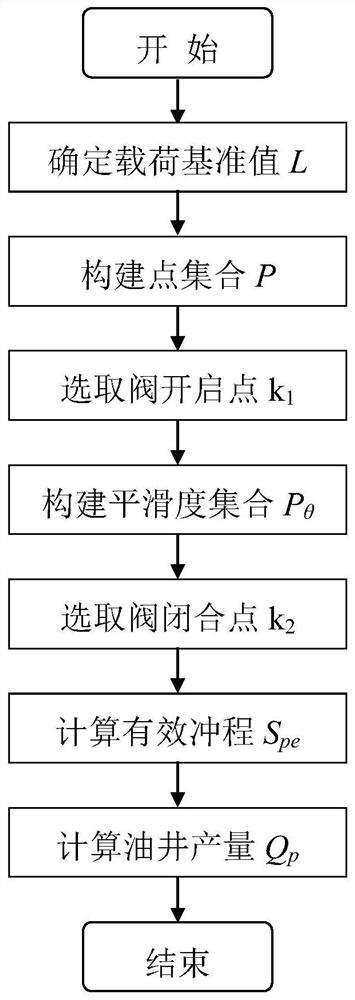
This method provides a method to directly calculate the production of heavy oil wells by using the ground dynamometer diagram without increasing hardware investment, and solves the problem that the production of single wells in heavy oil reservoirs is difficult to measure continuously and accurately

Method used


Image

  • A Method for Calculating Heavy Oil Well Production Based on Surface Dynamometer Diagram
  • A Method for Calculating Heavy Oil Well Production Based on Surface Dynamometer Diagram
  • A Method for Calculating Heavy Oil Well Production Based on Surface Dynamometer Diagram

Examples


Embodiment 1

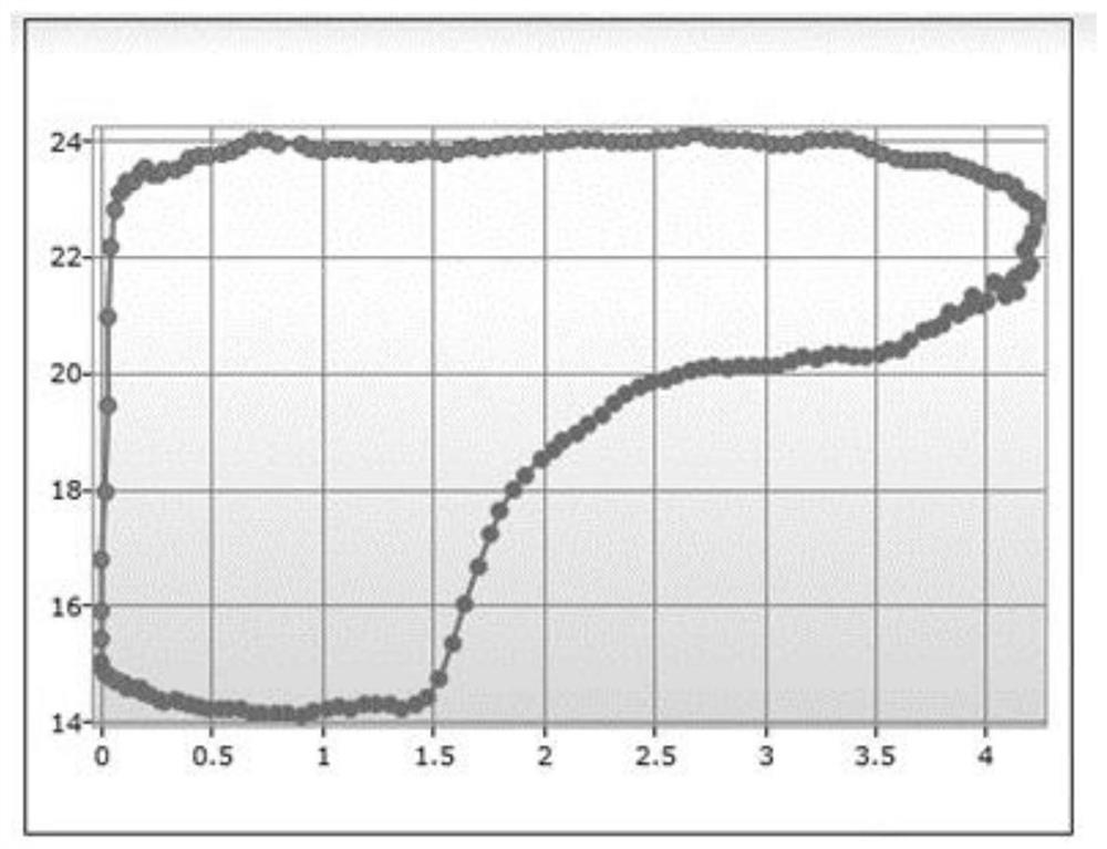
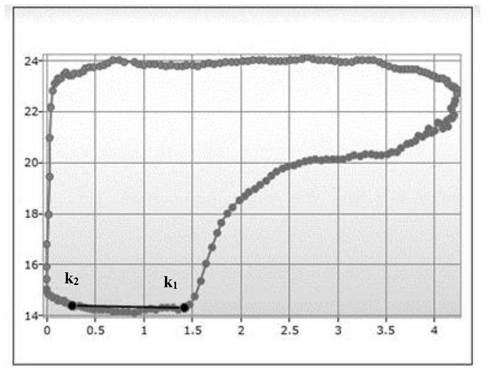
[0073]Heavy oil well GD in a block of Shengli Oilfield23, The degassed crude oil viscosity is 30562mPa.s, the pump diameter is 58mm, the stroke is 4.23m, the stroke is 2.78 times / min, the tested maximum load is 24.09kN, the minimum load is 14.08kN, and the well water cut is 34.5%. See the actual ground indicator diagram at 07:12 on May 6, 2017figure 2 , The indicator diagram data is shown in Table 1. The production of the oil well is calculated using the method of the present invention. Specific steps are as follows:

[0074]Table 1 Heavy oil well GD23Indicator diagram data

[0075]

[0076]

[0077]

[0078](1) Determine the load reference value L

[0079]L=(Lmax -Lmin ) / m+Lmin =(24.09-14.08) / 3+14.08=17.42kN

[0080]Among them, L-load reference value, kN;

[0081]Lmax -Maximum load, 24.09kN;

[0082]Lmin -Minimum load, 14.08kN;

[0083]m-reference coefficient, rounded, m=3.

[0084](2) According to the load reference value L, from n indicator diagram point pairs, where n=200, construct the indicator diagram point ...

Embodiment 2

[0122]Heavy oil well GD in a block of Shengli Oilfield12, Degassed crude oil viscosity 27600mPa.s, oil well pump diameter is 58mm, stroke is 4.19m, stroke is 2.72 times / min, tested maximum load is 26.46kN, minimum load is 8.95kN, oil well water cut is 65.0%. See the measured ground indicator diagram at 08:05 on July 8, 2017Figure 4 , The indicator diagram data is shown in Table 3. The production of the oil well is calculated using the method of the present invention. Specific steps are as follows:

[0123]Table 3 Heavy oil well GD12Indicator diagram data

[0124]

[0125]

[0126](1) Determine the load reference value L

[0127]L=(Lmax -Lmin ) / m+Lmin =(26.46-8.95) / 3+8.95=14.79kN

[0128]Among them, L-load reference value, kN;

[0129]Lmax -Maximum load, 26.46kN;

[0130]Lmin -Minimum load, 8.95kN;

[0131]m-reference coefficient, rounded, m=3.

[0132](2) According to the load reference value L, from n indicator diagram point pairs, where n=200, construct the indicator diagram point pair number set P that meets ...


PUM


Abstract

The invention belongs to the field of oil field production management and particularly relates to a method for calculating the yield of a thick oil well based on the ground dynamometer card. The method specifically comprises the following steps that a load datum value L is determined; according to the load datum value L, a dynamometer card point pair number set P meeting the condition is built from n dynamometer card point pairs; a valve opening point k1 is selected from the set P; the dynamometer card point pairs are read reversely, and a smoothness set P<theta> between a point i and the point k1 is worked out; the smoothness set P<theta> is analyzed, and a valve closing point k2 is selected; the effective stroke Spe is calculated through the point k1 and the point k2 which are determinedin the method; and the yield Qp of the thick oil well is calculated according to the oil pump displacement formula. According to the method for calculating the yield of the thick oil well based on the ground dynamometer card, the yield calculation procedure of the oil well is simplified, errors caused by intermediate conversion are avoided, the reliability, accuracy, continuity and real-time performance of measuring of the liquid yield of the thick oil well are guaranteed, the ground measuring process is simplified, and the oil field development investment and the oil field operation cost arereduced.

Description

Technical field[0001]The invention relates to the field of oilfield production management, in particular to a method for calculating the production of heavy oil wells based on a ground indicator diagram.Background technique[0002]The law of oil well production changes is an important basis for the evaluation of oil well production status, the analysis of changes in reservoir conditions, and the formulation of oilfield development plans. Real-time monitoring of oil well production occupies an important position in oilfield development. The traditional method of measuring the liquid volume of pumping wells is manual measurement using separators. Although this technology is simple in measuring equipment, it has a large investment in ground supporting construction and complicated operations. At the same time, the method of intermittent oil measurement is used to convert production, so it cannot be realized. Continuous metering of oil wells.[0003]At present, the surface indicator diagram ...

Claims


Application Information

Patent Timeline
Patent Type & Authority Patents(China)
IPC IPC(8): E21B47/00G06Q50/02
Inventor 孙辉刘恩新刘志兵杜伟邴绍强周娜张玉真尚岩巴永军顾静
Owner CHINA PETROLEUM & CHEM CORP
Why Eureka
Try Eureka