
Forward and backward motion type center shaft transmission mechanism

A motion-type, shaft-driven technology, applied in the direction of wheel transmission, chain/belt transmission, crank structure, etc., can solve redundant and other problems, and achieve the effect of reducing costs, reducing ineffective processes, and reducing complex mechanisms

Pending Publication Date: 2018-01-12
刘永安
View PDF0 Cites 0 Cited by
  • Summary
  • Abstract
  • Description
  • Claims
  • Application Information

AI Technical Summary

Problems solved by technology

[0003] The center shaft of the traditional riding driving method only acts as a fulcrum driving force for circular motion when riding. In the process of stepping on the maximum force angle on the force point, once the angle range exceeds the force point, Other angles are redundant movement process, just follow the transmission mechanism to do useless movement

Method used


Image

  • Forward and backward motion type center shaft transmission mechanism
  • Forward and backward motion type center shaft transmission mechanism
  • Forward and backward motion type center shaft transmission mechanism

Examples


Embodiment Construction

[0024] The present invention will be described in detail below in conjunction with the accompanying drawings and specific embodiments.

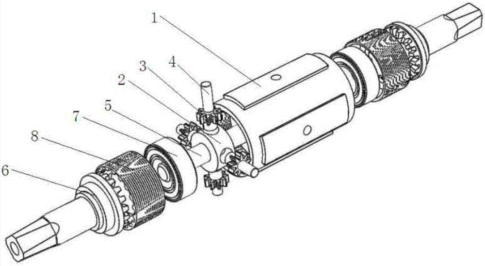
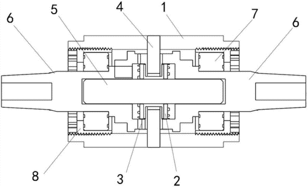
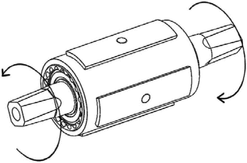
[0025] like Figure 1 to Figure 3 As shown, a forward and reverse movement center shaft transmission mechanism, the mechanism includes a center shaft cylinder 1, a circular cross 2 located inside the center shaft cylinder 1, an engaging pinion 3 and a section gear 6, the engaging The pinion 3 is installed around the circular cross 2, and the middle part of the circular cross 2 is pierced with a cross-section gear central shaft 5, and the two ends of the cross-section gear central shaft 5 are respectively sleeved with cross-section gears 6, and the cross-section gear 6 The gear end is sleeved on the end of the cross-section gear central shaft 5 and meshes with the meshing pinion 3. The shaft end of the cross-section gear 6 protrudes from the central shaft cylinder 1, and the shaft end is located on the central shaft cylinder 1. The inner part...


PUM


Abstract

The invention discloses a forward and backward motion type center shaft transmission mechanism. The forward and backward motion type center shaft transmission mechanism comprises a center shaft cylinder, a circular cross, occlusion small gears and fracture-surface gears, wherein the circular cross, the occlusion small gears and the fracture-surface gears are located in the center shaft cylinder. The occlusion small gears are installed on the periphery of the circular cross, a fracture-surface gear center shaft penetrates through the middle of the circular cross, and the fracture-surface gearsare installed at the two ends of the fracture-surface gear center shaft correspondingly in a sleeving mode; and the gear ends of the fracture-surface gears are installed at the two ends of the fracture-surface gear center shaft in a sleeving mode and engaged with the occlusion small gears, the rotary shaft ends of the fracture-surface gears extend out of the center shaft cylinder, the portions, inthe center shaft cylinder, of the rotary shaft ends are sequentially sleeved with bearings and center shaft locking covers, and the fracture-surface gears are fixed to the two ends of the center shaft cylinder through the center shaft locking covers. According to the forward and backward motion type center shaft transmission mechanism, the transmission efficiency is improved, the invalid processin the transmission process is reduced, the forward and backward motion type center shaft transmission mechanism can be applied to different fields, the cost of the transmission efficiency can be maximally reduced, and the number of complex mechanisms needing to achieve reciprocating motion in the transmission process is decreased.

Description

technical field [0001] The invention belongs to the field of mechanical transmission, and relates to a forward and reverse movement mode of a center shaft transmission mechanism, specifically a forward and reverse movement center shaft transmission mechanism; according to different fields of application, it can be driven by human power or can be It is driven by a motor or other transmission force. Background technique [0002] Traditional bicycle drive mode all is to do the drive of stepping on the circle mode. With the development of technology, there are also some technologies that continuously improve the driving method of bicycles. But according to known drive mode, also do not have a kind of drive mode that belongs to the present invention. [0003] The center shaft of the traditional riding driving method only serves as the fulcrum driving function for circular motion when riding. In the process of stepping on the maximum force angle on the force point, once the angl...

Claims


Application Information

Patent Timeline
IPC IPC(8): B62M11/02B62M9/02B62M3/00
Inventor 刘永安孙东晓郁榴明郑珉
Owner 刘永安
Learn More