
Automatic feeding and cut-off machine for material belts

An automatic feeding and cutting machine technology, applied in metal processing and other directions, can solve the problems of large error and low cutting efficiency of workers, and achieve the effect of small cutting error, high cutting efficiency and avoiding wear and tear.

Active Publication Date: 2018-01-12
平湖市宇达精密机械有限公司
View PDF4 Cites 4 Cited by
  • Summary
  • Abstract
  • Description
  • Claims
  • Application Information

AI Technical Summary

Problems solved by technology

[0003] In the existing situation, workers generally manually position the strips before cutting, but the small sections of strips cut out manually have large errors, and the cutting efficiency of workers is low.

Method used


Image

  • Automatic feeding and cut-off machine for material belts
  • Automatic feeding and cut-off machine for material belts
  • Automatic feeding and cut-off machine for material belts

Examples


Embodiment Construction

[0034] The present invention will be described in further detail below in conjunction with the accompanying drawings.

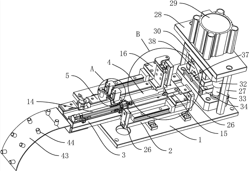
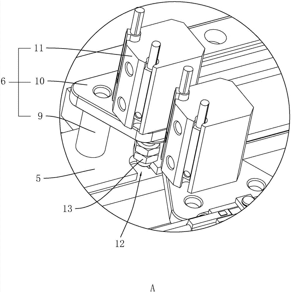
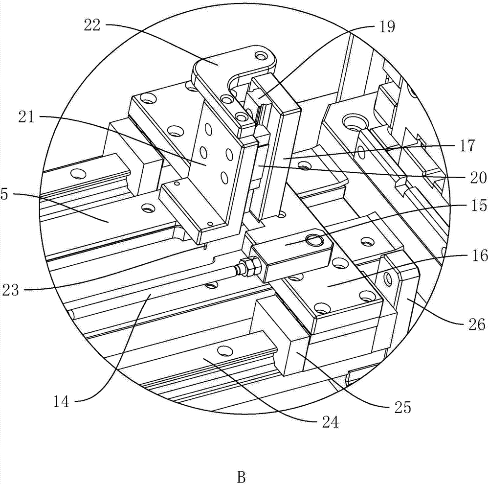
[0035] Such as figure 1 As shown, a material belt automatic feeding and cutting machine includes a bottom plate 1 for installation and fixing, the bottom plate 1 is horizontally arranged, and two parallel support bars are fixedly connected on the bottom plate 1, and a fixed plate 2 is supported on the support bar. The length direction of the plate 2 is perpendicular to the length direction of the support bar, and the support bar is used to support the fixed plate 2, so that the lines can be passed between the fixed plate 2 and the bottom plate 1. A guide plate 3 is fixed on the upper surface of the fixed plate 2, the length direction of the guide plate 3 is consistent with the length direction of the fixed plate 2, and a stepped groove 4 arranged along the length direction of the guide plate 3 is arranged in the middle of the upper surface of the guide plate 3...


PUM


Abstract

The invention discloses an automatic feeding and cut-off machine for material belts. The problems of low shearing efficiency and large shearing error of an existing material belt during shearing are solved. According to the technical scheme, the automatic feeding and cut-off machine for the material belts comprises a baseplate, and the upper surface of the baseplate is fixedly provided with a fixed plate; the upper surface of the fixed plate is fixedly provided with guide plates, and the middle positions of the upper surfaces of the guide plates are provided with stepped grooves arranged in the length direction of the guide plates; the guide plates on both sides of the stepped grooves are also fixedly provided with batten plates of which both ends are upturned, and a pressing device and afeeding device are arranged above the batten plates in sequence; and the baseplate is also fixedly provided with a shearing device used for shearing the material belts following the feeding device. The automatic feeding and cut-off machine disclosed by the invention is rational in structure, and the material belts are prevented from shifting through the pressing device; the accurate feeding of thematerial belts is ensured through the feeding device, and then the material belts are sheared accurately through the shearing device, so that the shearing efficiency of the material belts is high, and the shearing error of the material belts is small.

Description

technical field [0001] The invention relates to a cutting device, in particular to an automatic feeding and cutting machine for material tape. Background technique [0002] Such as Figure 7 As shown, it is a material tape produced by a precision electronic component 1. The two ends of the connecting wire of the precision electronic component 1 are respectively connected to the two side strips 2 of the material strip, and the two side strips 2 of the material strip are also connected Positioning holes 3 arranged at equal intervals are provided. After the material tape is produced, it needs to be cut into small pieces, and then the subsequent precision injection molding or other operations are performed. [0003] In the existing situation, the worker manually positions the tape before cutting, but the small section of the tape cut out manually has a large error, and the cutting efficiency of the worker is low. Contents of the invention [0004] The object of the present i...

Claims


Application Information

Patent Timeline
Patent Type & Authority Applications(China)
IPC IPC(8): B26D1/06B26D7/06B26D7/02B26D5/12B26D7/00
Inventor 曹勇章向宗海杨森
Owner 平湖市宇达精密机械有限公司
Learn More