
Parallel operation system for reactive power compensation devices and reactive power compensation control method

A compensation device and operating system technology, applied in the direction of reactive power adjustment/elimination/compensation, flexible AC transmission system, etc., can solve the problems such as the inability of the supplementary capacity of the SVG device to meet the needs of users, and the increased hardware cost of multiple coordination controllers, etc. Achieve the effect of improving work efficiency and reliability, increasing capacity, and reducing hardware costs

Active Publication Date: 2018-01-09
XJ ELECTRIC +2
View PDF5 Cites 7 Cited by
  • Summary
  • Abstract
  • Description
  • Claims
  • Application Information

AI Technical Summary

Problems solved by technology

[0010] The purpose of the present invention is to provide a reactive power compensation device parallel operation system and reactive power compensation control method, which is used to solve the problem that the supplementary capacity of a single SVG device cannot meet the needs of users, and multiple SVG devices need multiple Problems with Coordinating Controllers Adding Hardware Costs

Method used


Image

  • Parallel operation system for reactive power compensation devices and reactive power compensation control method
  • Parallel operation system for reactive power compensation devices and reactive power compensation control method
  • Parallel operation system for reactive power compensation devices and reactive power compensation control method

Examples


Embodiment Construction

[0039] The specific embodiments of the present invention will be further described below in conjunction with the accompanying drawings.

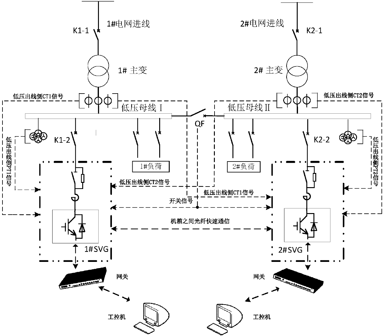
[0040] Such as figure 1The transformer parallel operation system shown includes two transformers, namely No. 1 main transformer and No. 2 main transformer. The parallel side of No. 1 main transformer and No. 2 main transformer is the low-voltage side, and the parallel side of No. 1 main transformer is equipped with The low-voltage bus Ⅰ is connected with No. 1 SVG (reactive power compensation device), and the parallel side of No. 2 main transformer is equipped with low-voltage bus II, which is connected with No. 2 SVG. In order to improve the reliability of power supply, the two sections of low-voltage busbars are respectively powered by the high-voltage side grid of the transformer, and the two SVGs are respectively directly connected to the two sections of low-voltage side busbars. When the circuit breaker is disconnected, No. 1 SVG and N...


PUM


Abstract

The invention relates to a parallel operation system for reactive power compensation devices and a reactive power compensation control method. Two transformers run in parallel; buses corresponding tothe transformers are connected with the reactive power compensation devices; the buses are connected through a bus tie breaker; and the adopted reactive power compensation control method comprises thesteps of adopting one reactive power compensation device as a host and the other reactive power compensation devices as slaves; and detecting current and reactive power on all buses by the host and determining to-be-compensated reactive current of the host and the slaves according to the operation modes of all reactive power compensation devices. Compared with a single SVG, the system has the advantage that the capacity of the system is increased; and due to parallel arrangement of the transformers, two SVGs are divided into the host and the slave and communicate with each other, and reactivepower compensation current is distributed between the host and the slave.

Description

technical field [0001] The invention belongs to the technical field of electric power electronic control, and in particular relates to a reactive power compensation device parallel operation system and a reactive power compensation control method. Background technique [0002] Since entering the 21st century, my country's economy has developed rapidly, and the power system, which is the basis of the national economy, has also become larger and larger due to the continuous increase in demand. In all walks of life in modern times, the demand and dependence on electricity are becoming more and more intense, and the power system has also developed rapidly. There is a large amount of reactive power flowing in the huge power system, which generates a lot of loss, causes voltage drop, and affects the quality of power energy. This will cause adverse effects on the entire power system from power generation to power supply, and power distribution. The main manifestations are as follow...

Claims


Application Information

Patent Timeline
IPC IPC(8): H02J3/18
CPCY02E40/10
Inventor 胡四全刘刚孙健许恩泽臧兴平左广杰高志军许明阳李继凯卢海亮王志伟李亚鹏
Owner XJ ELECTRIC
Learn More