
Electrical Connector Assembly

A technology of electrical connectors and components, applied in the direction of electrical connection of printed components, connections, printed circuit components, etc., can solve the problems of increased electrical signal loss, electrical signal loss, and large electrical signal loss, and achieve improved Efficiency, reduce loss, deliver good results

Active Publication Date: 2019-04-30
DEYI PRECISION ELECTRONIC IND CO LTD PANYU
View PDF5 Cites 0 Cited by
  • Summary
  • Abstract
  • Description
  • Claims
  • Application Information

AI Technical Summary

Problems solved by technology

After soldering, a part of the solder is located on the remaining area and the terminal is fixed to the pad. After part of the electrical signal passes through the connection part of the terminal, it is transferred to the remaining area by the connection part through the solder, so that this part of the signal faces the remaining area opposite to the electrical lead. Transmission, the signal transmission path is equivalent to an invalid branch path, resulting in the loss of electrical signals
The longer the remaining area, the greater the electrical signal loss
At the same time, the electrical signal is transmitted from the welding part to the transmission area of ​​the gasket. The longer the transmission area, the longer the transmission path of the electrical signal, and the greater the loss of the electrical signal.

Method used


Image

  • Electrical Connector Assembly
  • Electrical Connector Assembly
  • Electrical Connector Assembly

Examples


Embodiment Construction

[0034] In order to facilitate a better understanding of the purpose, structure, features, and effects of the present invention, the present invention will now be further described in conjunction with the accompanying drawings and specific embodiments.

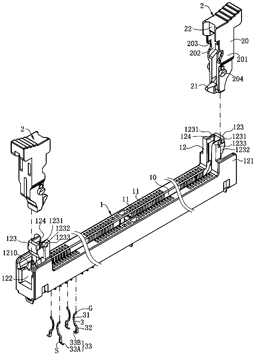
[0035] see figure 1 with figure 2, which is the prior technology of the present invention, the electrical connector assembly 100' is docked with an electronic card (not shown) to realize the transmission of electrical signals. The electrical connector assembly 100' includes an insulating body 1' (not shown), and the insulating body 1' has a downwardly recessed slot 10' for receiving the electronic card (not shown). . A plurality of terminals 3' are arranged in two rows on opposite sides of the slot 10'. Each row of the terminals 3' has a plurality of first soldering portions 33A' and a plurality of second soldering portions 33B', and the first soldering portions 33' and the second soldering portions 34' are arranged along t...


PUM


Abstract

The invention discloses an electrical connector assembly, comprising a first gasket and a second gasket, wherein the first gasket is provided with a first area and is far from an electrical lead relative to a contact area, the second gasket is provided with a second area and is close to the electrical lead relative to the contact area, the first area has a first border, the projection of the firstborder in the longitudinal direction falls into the projection range of the second area in the longitudinal direction, the first area is shortened, and the invalid branch formed on the first gasket and used for electrical signal transmission becomes short, so that the electrical lead is good in transmission and the loss of electrical signals is reduced. The second area has a second border, the projection of the second border in the longitudinal direction falls into the projection range of the first area in the longitudinal direction, the second area is shortened, and the transmission path ofelectrical signals on the second gasket becomes short, so that the transmission efficiency of the electrical signals is improved and the loss of the electrical signals is reduced.

Description

technical field [0001] The invention relates to an electrical connector assembly, in particular to an electrical connector assembly with good electrical signal transmission effect. Background technique [0002] An electrical connector assembly is known, which is connected to an electronic card for transmitting electrical signals. It has an insulating body, and a slot recessed downwards in the insulating body is used for accommodating the electronic card. A plurality of terminals are arranged on the insulating body and located on two opposite sides of the slot. Each terminal has a connection portion, a contact portion extends upward from the connection portion, the contact portion protrudes into the slot for electrical contact with the electronic card, and a welding portion extends downward from the connection portion. A circuit board, the insulating body is installed on the circuit board, the surface of the circuit board has a plurality of gaskets, and one side of the gask...

Claims


Application Information

Patent Timeline
Patent Type & Authority Patents(China)
IPC IPC(8): H01R12/73H05K1/11
Inventor 朱德祥蔡友华
Owner DEYI PRECISION ELECTRONIC IND CO LTD PANYU
Learn More