Eureka AIR delivers breakthrough ideas for toughest innovation challenges, trusted by R&D personnel around the world.

Method and apparatus for fouling monitoring and prediction in combustors

A monitoring device and burner technology, which are used in gas turbine engine testing, jet engine testing, etc., can solve the problems of burner nozzle fouling, which is difficult to be directly monitored, fouling, and unstable combustion, so as to save research funds and use cost effect

Active Publication Date: 2020-10-16
SIEMENS ENERGY GLOBAL GMBH & CO KG
View PDF10 Cites 0 Cited by
  • Summary
  • Abstract
  • Description
  • Claims
  • Application Information

AI Technical Summary

Problems solved by technology

Poor gas quality can cause fouling in such small holes
[0003] Currently, fouling in the burner nozzle is difficult to monitor directly without shutting down the gas turbine and opening the gas turbine casing and inspecting the burner
Obviously, in practical situations, the above method cannot be frequently applied for burner fouling monitoring, and the generated deposits (i.e. fouling) may lead to insufficient mass flow to the combustion chamber , which will lead to unstable combustion

Method used


Image

  • Method and apparatus for fouling monitoring and prediction in combustors
  • Method and apparatus for fouling monitoring and prediction in combustors
  • Method and apparatus for fouling monitoring and prediction in combustors

Examples


Embodiment Construction

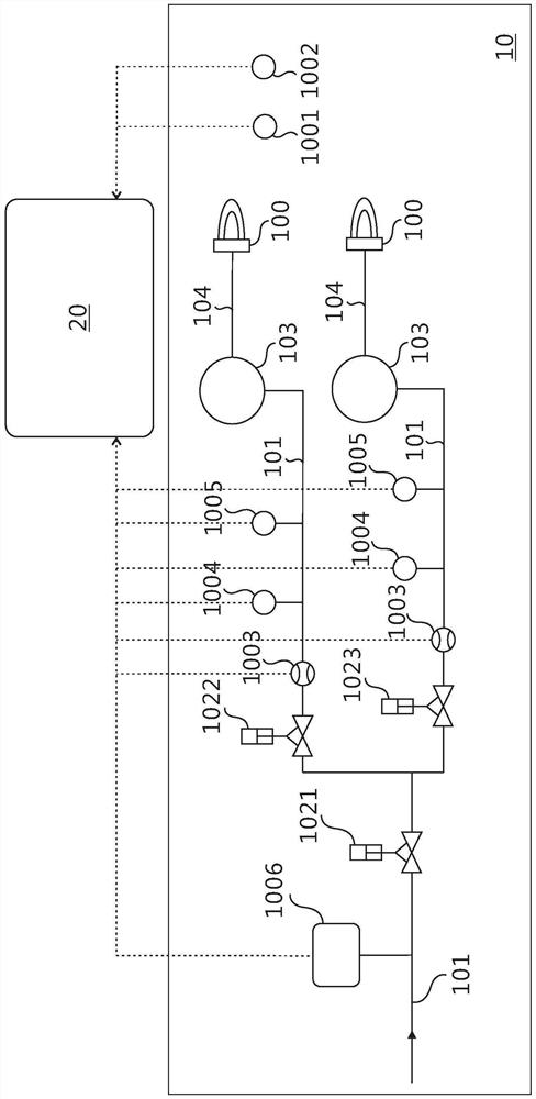
[0038] Preferred embodiments of the present disclosure will be described in more detail below with reference to the accompanying drawings. Although preferred embodiments of the present disclosure are shown in the drawings, it should be understood that the present disclosure may be embodied in various forms and should not be limited to the embodiments set forth herein. Rather, these embodiments are provided so that this disclosure will be thorough and complete, and will fully convey the scope of the disclosure to those skilled in the art.

[0039]After reading the following description it will be apparent to those skilled in the art that the teachings of the present invention can be readily applied to burner or gas systems in general. The method, system and device described in the present invention are applicable to all kinds of burners. Preferably, the present invention can be applied in a gas turbine (Gas Turbine).

[0040] Here, the fouling mentioned in the present inventi...


PUM


Abstract

The invention provides a method and device used for monitoring and predicting scales in a combustor. The method comprises steps of by acquiring one kind of or various kinds of combustion signals of the combustor and / or a gas system corresponding to the combustor; determining combustor performance models corresponding to the combustion state signals according to the combustion signals; acquiring acombustor performance reference model corresponding to the combustor; and finally, according to the combustor performance model, by combining the combustor performance reference model, determining early warning information corresponding to the combustor. Thus, the generated combustor performance model is quite practical; by use of the method and the device, large quantity of research funds and usecost can be reduced; the scales and the development trend of the combustor can be monitored and predicted in a quite simple and convenient mode; and the method and the device can be used for strategyplanning of maintenance of economical combustors or gas turbines.

Description

technical field [0001] The invention relates to the field of gas turbine burners and gas systems, in particular to a method and device for monitoring and predicting fouling in the burner. Background technique [0002] Typically, in a gas turbine gas system, the gas flow path of the following two components contains holes with a small flow diameter: one is the control valve and the other is the burner. Poor gas quality can cause fouling in such small holes. [0003] Currently, fouling in combustor nozzles is difficult to monitor directly without shutting down the gas turbine and opening the gas turbine casing and inspecting the combustor. Obviously, in practical situations, the above method cannot be frequently applied for burner fouling monitoring, and the generated deposits (i.e. fouling) may lead to insufficient mass flow to the combustion chamber , which will lead to unstable combustion. Contents of the invention [0004] In view of this, one of the problems solved b...

Claims


Application Information

Patent Timeline
Patent Type & Authority Patents(China)
IPC IPC(8): G01M15/14
Inventor 吕松军佰恩德·普拉德
Owner SIEMENS ENERGY GLOBAL GMBH & CO KG
Why Eureka
Eureka Blog
Learn More