
Anticorrosion flow guide structure for natural gas wells

A technology of natural gas and liquid inlet holes, which is applied in wellbore/well components, wellbore/well valve devices, earthwork drilling and production, etc. It can solve wellhead overflow, oil and gas flow drilling failure, and difficult operation of high-pressure oil and gas lamination wells To prevent wellhead overflow, reduce the probability of occurrence, and avoid well control disorders

Inactive Publication Date: 2018-01-09
成都瞬科仪器仪表有限公司
View PDF8 Cites 0 Cited by
  • Summary
  • Abstract
  • Description
  • Claims
  • Application Information

AI Technical Summary

Problems solved by technology

[0002] When drilling into an oil and gas formation with abnormal high pressure, the oil flow in the high pressure oil and gas formation moves upwards under the pressure and drives the mud to the wellhead together. The upward movement of the oil flow causes drilling failure. Otherwise, the well control will be out of control. Usually, it is easy to cause a blowout accident, and the well killing operation of the high-pressure oil and gas layer is not easy to carry out, which disturbs the normal operation of the drilling production operation.

Method used


Image

  • Anticorrosion flow guide structure for natural gas wells
  • Anticorrosion flow guide structure for natural gas wells
  • Anticorrosion flow guide structure for natural gas wells

Examples


Embodiment 1

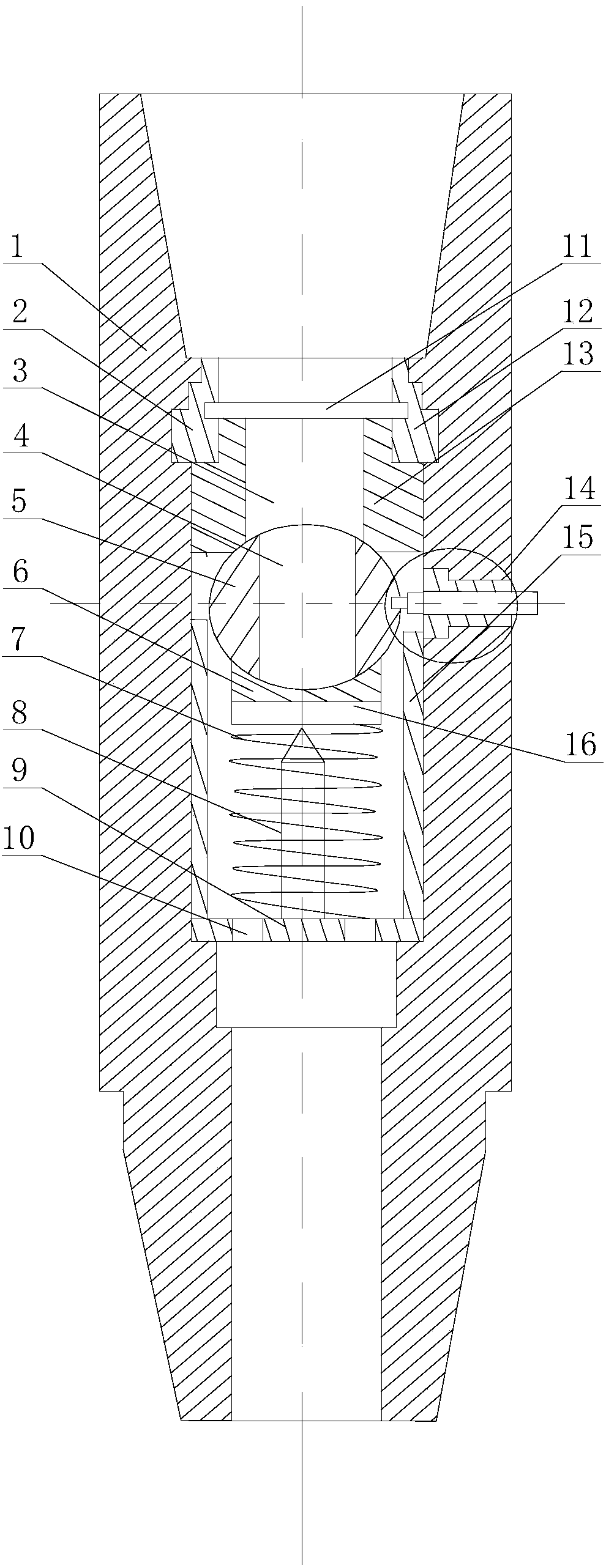
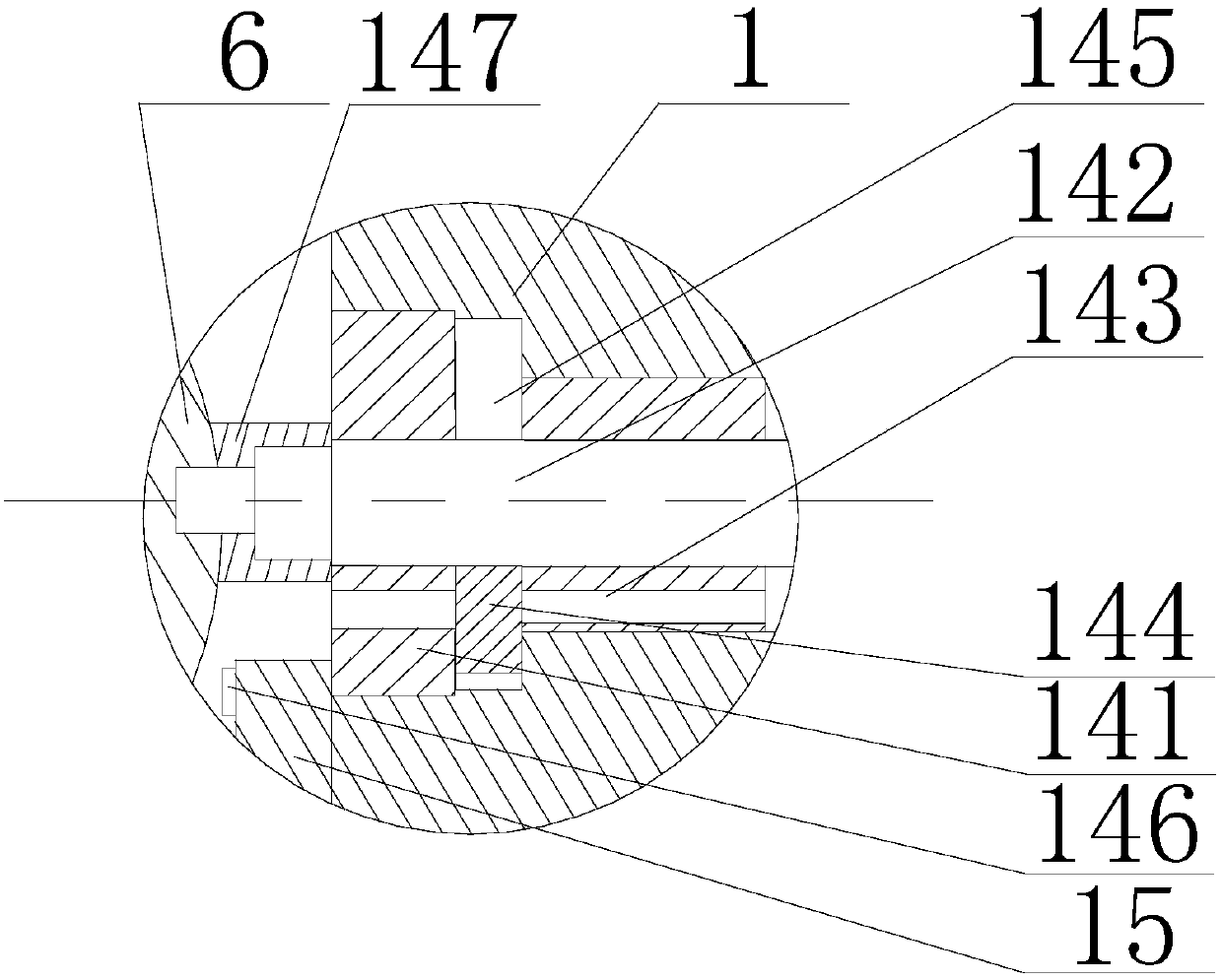
[0021] Such as Figure 1~3 As shown, this embodiment includes a cylinder body 1, a bottom plate 9, a sphere 5 and an upper ball seat 13, and a liquid inlet hole 3 is opened inside the cylinder body 1, and the bottom plate 9 is fixed on the bottom of the liquid inlet hole 3, and the upper The ball seat 13 is fixed on the upper part of the liquid inlet hole 3 and communicates with the liquid inlet hole 3 inside. A support shaft 8 is arranged in the middle of the bottom plate 9. The spring 7 is sleeved on the support shaft 8. There are a plurality of small holes on the bottom plate 9. 10. The top of the spring 7 is provided with a limit plate 16, and there is a gap between the bottom of the limit plate 16 and the top of the support shaft 8. The upper end of the support shaft 8 is provided with an elastic cone 18, and the bottom surface of the limit plate 16 is embedded with a facing The rubber block 17 of the cone 18, the lower ball seat 6 is fixed on the limit plate 16, a spheri...


PUM


Abstract

The invention discloses an anticorrosion flow guide structure for natural gas wells. The anticorrosion flow guide structure comprises a barrel, a bottom plate, a ball and an upper ball seat. A liquidinlet hole is formed inside the barrel, the bottom plate is fixed to the lower portion of the liquid inlet hole, the upper ball seat is fixed to the upper portion of the liquid inlet hole, the insideof the ball seat is communicated with the liquid inlet hole, a support shaft is arranged in the middle of the bottom plate, a spring sleeves the support shaft, a plurality of small holes are formed inthe bottom plate, a limit plate is arranged on the top of the spring, gaps are reserved between the bottom of the limit plate and the top of the support shaft, a lower ball seat is fixed onto the limit plate, and a through hole which is communicated with the liquid inlet hole is formed in the middle of the ball; a connecting shaft is rotationally arranged in a sleeve, and an end of the connectingshaft is connected with the upper portion of the ball. The anticorrosion flow guide structure has the advantages that the sizes of communication cross sections of the liquid inlet hole can be adjusted by an adjusting mechanism, accordingly, channeling oil and gas can be blocked, aggregation of wellhead overflow or well kick accidents due to oil and gas flow channeling can be prevented, and well control imbalance can be prevented.

Description

technical field [0001] The invention relates to the field of gas field exploitation, in particular to an anti-corrosion diversion structure for natural gas wells. Background technique [0002] When drilling into an oil and gas formation with abnormal high pressure, the oil flow in the high pressure oil and gas formation moves upwards under the pressure and drives the mud to the wellhead together. The upward movement of the oil flow causes drilling failure. Otherwise, the well control will be out of control. Usually, it is easy to cause a blowout accident, and the well killing operation of the high-pressure oil and gas layer is not easy to carry out, which disturbs the normal operation of drilling and production operations. Contents of the invention [0003] The object of the present invention is to provide an anti-corrosion diversion structure for natural gas wells to solve the above-mentioned defects. [0004] The present invention realizes through following technical sc...

Claims


Application Information

Patent Timeline
IPC IPC(8): E21B33/06E21B34/02
Inventor 邓怡
Owner 成都瞬科仪器仪表有限公司
Learn More