A radio frequency transformer for transforming an input radio frequency signal into an output radio frequency signal

A technology of radio frequency transformer and radio frequency signal, which is applied in the direction of fixed transformer or mutual inductance, parts of transformer/inductor, transformer/inductor coil/winding/connection, etc., which can solve the problem of reducing the performance of radio frequency transmitter and achieve the reduction of common mode The effect of impedance

Active Publication Date: 2018-01-05
HUAWEI TECH CO LTD
View PDF6 Cites 0 Cited by
  • Summary
  • Abstract
  • Description
  • Claims
  • Application Information

AI Technical Summary

Problems solved by technology

However, the common RF transformer has a common-mode shunt resonance at nearly twice the differential-mode resonance frequency, degrading the performance of the RF transmitter

Method used


Image

  • A radio frequency transformer for transforming an input radio frequency signal into an output radio frequency signal
  • A radio frequency transformer for transforming an input radio frequency signal into an output radio frequency signal
  • A radio frequency transformer for transforming an input radio frequency signal into an output radio frequency signal

Examples


Embodiment Construction

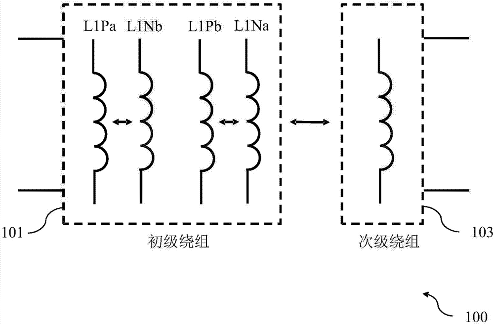
[0054] figure 1 Shown is a diagram of a radio frequency transformer 100 for transforming an input radio frequency signal into an output radio frequency signal according to an embodiment.

[0055] The radio frequency transformer 100 includes a primary winding 101 having a first input terminal and a second input terminal, wherein: the first input terminal and the second input terminal are used to process an input radio frequency signal, and the primary winding 101 includes a first part L1Pa, a second part L1Pb, The third part L1Na and the fourth part L1Nb, the first part L1Pa is electromagnetically coupled to the fourth part L1Nb, and the second part L1Pb is electromagnetically coupled to the third part L1Na.

[0056] The radio frequency transformer 100 also includes a secondary winding 103 having a first output terminal and a second output terminal, wherein: the first output terminal and the second output terminal are used to provide an output radio frequency signal, and the se...


PUM


Abstract

The invention relates to a radio frequency transformer (100) for transforming an input radio frequency signal into an output radio frequency signal, the radio frequency transformer (100) comprising aprimary winding (101) having a first input terminal and a second input terminal, wherein the primary winding (101) comprises a first portion (L1Pa), a second portion (L1Pb), a third portion (L1Na), and a fourth portion (L1Nb), wherein the first portion (L1Pa) is electromagnetically coupled to the fourth portion (L1Nb), and wherein the second portion (L1Pb) is electromagnetically coupled to the third portion (L1Na), and a secondary winding (103) having a first output terminal and a second output terminal, wherein the secondary winding (103) is electromagnetically coupled to the first portion (L1Pa), the second portion (L1Pb), the third portion (L1Na), and the fourth portion (L1Nb) of the primary winding (101).

Description

technical field [0001] The present invention relates to the field of radio frequency transformers, in particular to radio frequency transformers for switching between balanced and unbalanced terminals. Background technique [0002] RF transformers are an essential component in radio frequency (RF) systems, such as mobile communication systems or radar systems, and are used in a wide variety of applications. Typically, RF transformers are used for impedance transformation between primary and secondary windings and for transformation between balanced and unbalanced terminals. [0003] Specifically, RF transformers are commonly used in RF transmitters and can have a significant impact on their performance. For example, a digital RF transmitter using a direct digital radio frequency modulator (DDRM) or an analog RF transmitter using a 25% duty cycle mixer would want low common-mode impedance so that the input RF Terminate strong common-mode currents at multiple frequencies. H...

Claims


Application Information

Patent Timeline
Patent Type & Authority Applications(China)
IPC IPC(8): H01F19/04H01F27/28H01F27/34
CPCH01F19/04H01F27/2804H01F27/34
Inventor 乌多·卡索斯卡尔-弗雷德里克·宾克
Owner HUAWEI TECH CO LTD
Why Eureka
Try Eureka