
Rotor core and motor with same

A technology of rotor iron core and rotor punching, applied in the field of rotor iron core and motors with it, can solve the problems of easy loosening of magnetic steel, and achieve the effect of improving stability and reliability

Active Publication Date: 2021-05-28
ZHUHAI GREE REFRIGERATION TECH CENT OF ENERGY SAVING & ENVIRONMENTAL PROTECTION
View PDF6 Cites 0 Cited by
  • Summary
  • Abstract
  • Description
  • Claims
  • Application Information

AI Technical Summary

Problems solved by technology

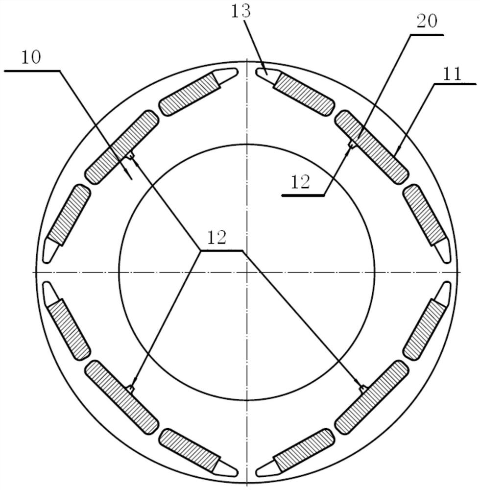
[0005] The main purpose of the present invention is to provide a rotor core and a motor with it, so as to solve the problem that the magnetic steel of the rotor core is easy to loosen in the prior art

Method used


Image

  • Rotor core and motor with same
  • Rotor core and motor with same
  • Rotor core and motor with same

Examples


Embodiment Construction

[0025] It should be noted that the embodiments in the present application and the features of the embodiments may be combined with each other in the case of no conflict. The present invention will be described in detail below with reference to the accompanying drawings and in conjunction with the embodiments.

[0026] It should be noted that the terminology used herein is for the purpose of describing specific embodiments only, and is not intended to limit the exemplary embodiments according to the present application. As used herein, unless the context clearly dictates otherwise, the singular is intended to include the plural as well, furthermore, it is to be understood that when the terms "comprising" and / or "including" are used in this specification, it indicates that There are features, steps, operations, devices, components and / or combinations thereof.

[0027] It should be noted that the terms "first", "second" and the like in the description and claims of the present a...


PUM


Abstract

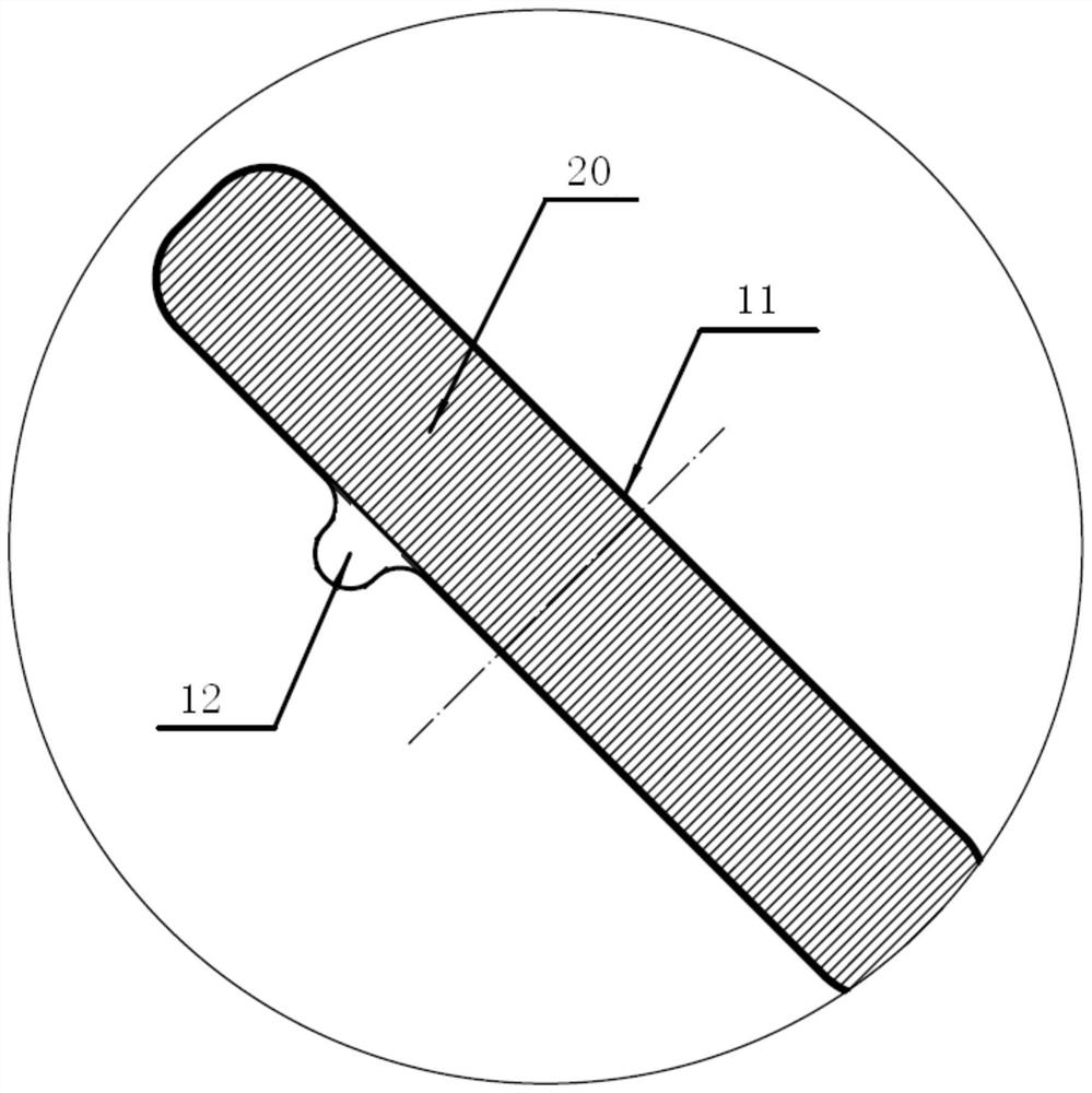
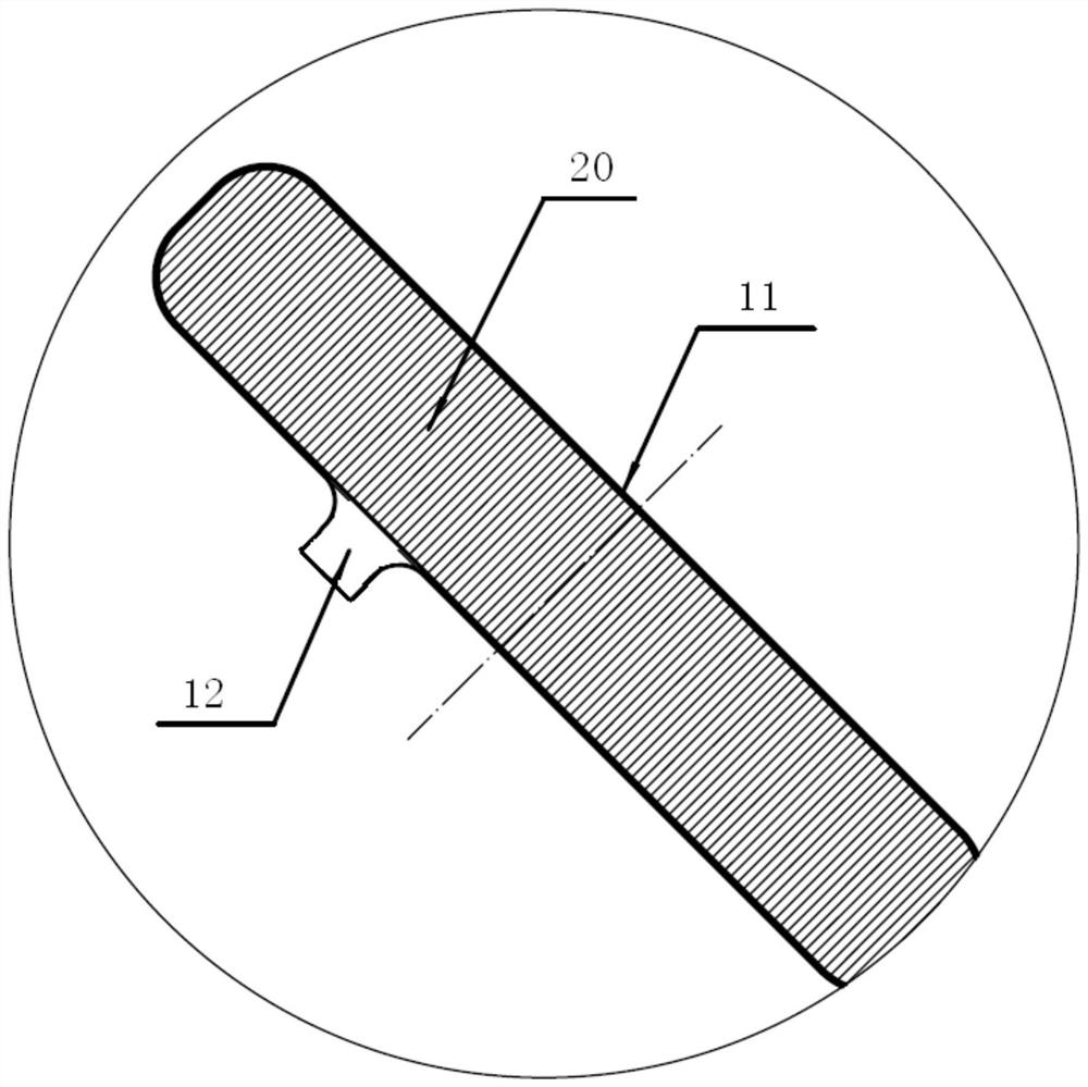
The invention provides a rotor iron core and a motor with the same. The rotor core includes: a rotor punch, on which there are multiple installation grooves for installing magnetic steel, and at least one of the multiple installation grooves is provided with a connecting groove on the wall of the groove. A connecting groove is provided on the groove wall of the mounting groove on the rotor punch, so that when the magnetic steel is installed in the mounting groove, whether it is dipped in paint or glued, the magnetic steel can be firmly installed on the magnetic steel. installed in the slot. Due to the arrangement of the dipping tank, the installation tank of the magnetic steel will not hold air during the installation process, so that the technical solution of the application is used to install the magnetic steel, and the magnetic steel can be installed in place without knocking on the magnetic steel. The stability and reliability of the rotor core are effectively improved.

Description

technical field [0001] The present invention relates to the technical field of electrical equipment, and in particular, to a rotor iron core and a motor having the same. Background technique [0002] In the prior art, the existing high-speed motor rotor core structure is composed of four parts, which are rotor punching pieces, magnetic steel installation grooves, installation grooves, and magnetic steel. The magnetic steel installation groove has different cross sections, and the gap between the magnetic steel and the installation groove is between 0.03mm and 0.1mm. After the rotor is assembled, the whole needs to be dipped in paint or fixed with magnetic steel glue during the assembly process. This is due to the high speed of the high-speed motor and the large centrifugal force, so the magnetic steel inside the rotor core needs to be fixed to prevent Magnetic steel flying out by centrifugal force. [0003] Using the method of dipping, after the rotor is dipped in paint, t...

Claims


Application Information

Patent Timeline
Patent Type & Authority Patents(China)
IPC IPC(8): H02K1/27H02K15/03
Inventor 闫瑾贾金信张小波刘健宁张芳李广海郭长光魏琼李忠雨
Owner ZHUHAI GREE REFRIGERATION TECH CENT OF ENERGY SAVING & ENVIRONMENTAL PROTECTION
Learn More