A precision micro-displacement detection device and method based on micro-lens moiré imaging
A detection device and micro-displacement technology, applied in the direction of measuring devices, optical devices, instruments, etc., can solve problems such as difficult measurement methods, and achieve the effects of flexible methods, simple mechanical mechanisms, and clear principles
- Summary
- Abstract
- Description
- Claims
- Application Information
AI Technical Summary
Problems solved by technology
Method used
Image
Examples
Embodiment 1
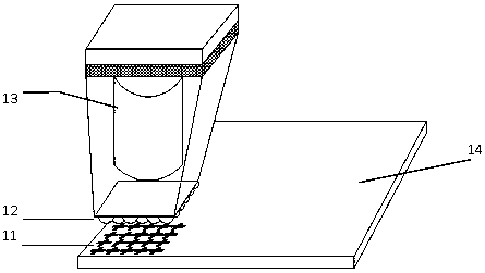
[0046] Embodiment one: see attached figure 1 As shown, a schematic diagram of a micro-displacement detection device based on the principle of Moire imaging. The detection table 14 carries the micro-image-text array area 11 for the detection of the micro-displacement of the moiré image of the present invention. The microlens array area 12 and the image recording mechanism 13 are located on another mechanical structure that can move relative to the platform to be tested. The micro-lens array area 12 is used to cooperate with the micro-text array area 11 on the detection table 14 to form a moiré image. The image recording mechanism 13 has the functions of illumination, image miniaturization and image recording. The relative translation and rotation between the detection table 14 and the image recording mechanism 13 will affect the position, size and orientation of the moiré image. The micro-text array area 11 of the platform to be tested is in the range of 50% to 150% of the f...
Embodiment 2
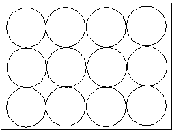
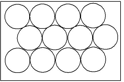
[0047] Embodiment two: see attached Figure 2a-2c As shown, a micro-displacement detection method based on the Moire imaging principle and a schematic diagram of the arrangement of the micro-lens array in the device. This arrangement can be a regular square arrangement, as attached Figure 2a shown, or a regular honeycomb arrangement, as attached Figure 2b shown; or non-periodic and irregular arrangement, as attached Figure 2c shown. The diameter of the microlens is 10 to 1000 microns, and the numerical aperture of the microlens is 0.1 to 4.0. In the preferred technical solution, the aperture size of the microlens is 50 to 500 microns; the numerical aperture of the microlens is less than 2.0. Microlens arrays can be cylindrical, spherical or aspherical. The ratio of the area where the microlens is located to the total area is called the duty cycle. The higher the duty cycle, the higher the contrast of the enlarged graphics obtained. Such as Figure 2a The shown squar...
Embodiment 3
[0048] Embodiment three: see attached Figure 3a~3c As shown, a micro-displacement detection method based on the Moire imaging principle and a schematic diagram of the arrangement of the micro-text array in the device. The arrangement can be a regular square arrangement, as attached Figure 3a shown, or a regular honeycomb arrangement, as attached Figure 3b shown; or non-periodic and irregular arrangement, as attached Figure 3c shown. The micrographic array is composed of at least two of microprinted patterns, surface microrelief micropatterns filled with pigments or dyes, line structure micropatterns or printed patterns, surface microrelief micropatterns filled with pigments or dyes, and line structure micropatterns combination composition. The micro-text in the micro-text layer can be graphics, text, or a mixture of graphics and text; ordinary printed text can be used, and micro-nano structures can also be used, for example, it can be a one-dimensional grating, The gr...
PUM
 Abstract
Description
Claims
Application Information
 - R&D Engineer
- R&D Manager
- IP Professional
- Industry Leading Data Capabilities
- Powerful AI technology
- Patent DNA Extraction
Browse by: Latest US Patents, China's latest patents, Technical Efficacy Thesaurus, Application Domain, Technology Topic, Popular Technical Reports.
© 2024 PatSnap. All rights reserved.Legal|Privacy policy|Modern Slavery Act Transparency Statement|Sitemap|About US| Contact US: help@patsnap.com


