Indoor floor heating water collection and distribution device

A water collector and floor heating technology, which is applied in the fields of heating and building HVAC, can solve the problems of difficult disassembly and repair, high cost and poor appearance, etc., and achieves the effects of convenient installation and disassembly, labor saving, and simple structure

Inactive Publication Date: 2018-01-05
许军
View PDF0 Cites 1 Cited by
  • Summary
  • Abstract
  • Description
  • Claims
  • Application Information

AI Technical Summary

Problems solved by technology

[0002] The traditional floor heating collectors and distributors are basically made of metal materials that can be seen in the market, such as copper and stainless steel. These materials have poor thermal insulation performance, complicated processing technology, and relatively high cost prices. Socket or insert the hose on the distributor interface, and then tighten the hose through the metal hoop. The interface end of the hose needs to be specially installed and connected with a metal cap device to connect with the distributor. The technical dependence is relatively high. When the construction quality is not good, it will cause leakage. When the pipeline pressure is too high, it is easy to leak. The connection operation requires specialized skilled workers, auxiliary materials, special tools and other conditions. The time required for connection is also It is relatively long. In addition, when the metal threaded interface is used, the thread ring may burst or be screwed up when it is too tightened, resulting in the scrapping of the distributor. At the same time, the installation method of the existing traditional floor heating water collector is basically fixed. Outside the wall, the appearance is relatively poor, and the detachability and later maintenance are also relatively poor. It is not easy to disassemble and repair after a fault occurs

Method used


Image

  • Indoor floor heating water collection and distribution device
  • Indoor floor heating water collection and distribution device
  • Indoor floor heating water collection and distribution device

Examples


Embodiment Construction

[0011] The preferred embodiments of the present invention will be described in detail below in conjunction with the accompanying drawings, so that the advantages and features of the invention can be more easily understood by those skilled in the art, so as to define the protection scope of the present invention more clearly.

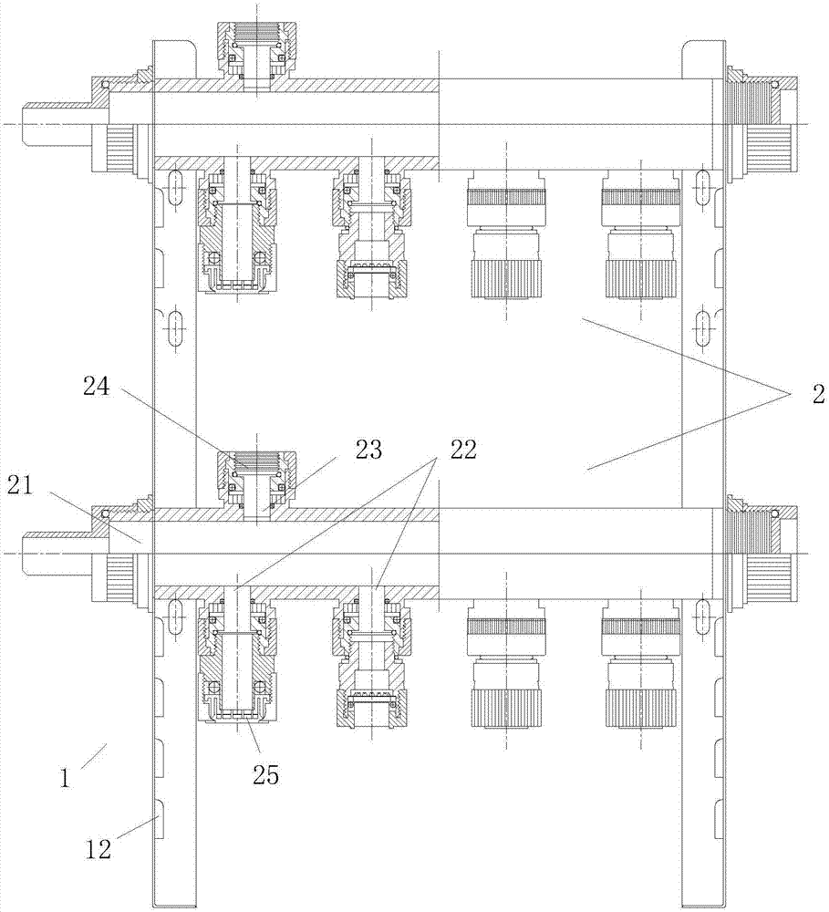
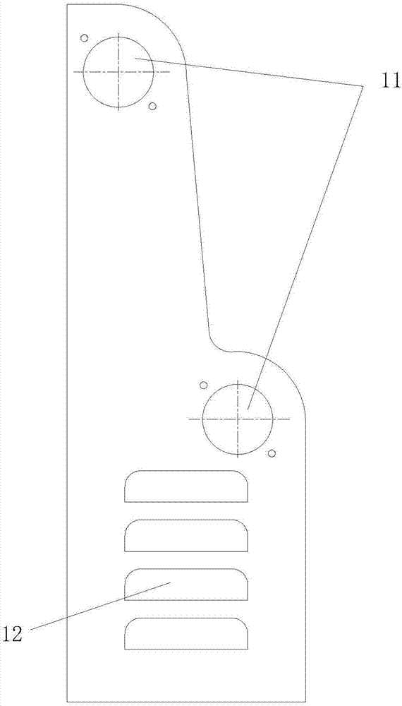
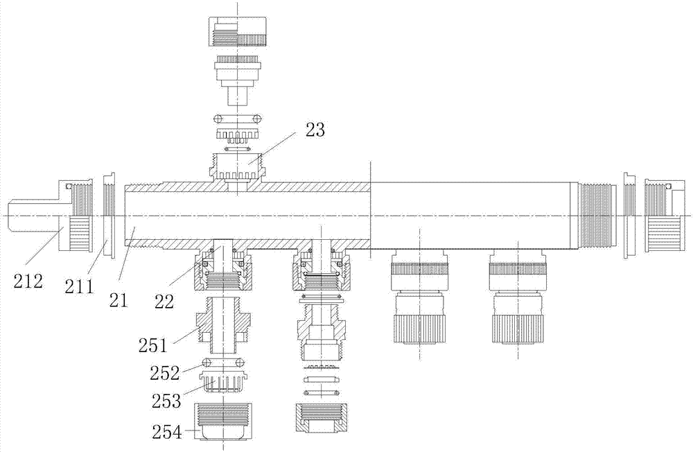
[0012] see Figure 1 to Figure 3 , the embodiment of the present invention includes:

[0013] An indoor floor heating water collecting and distributing device, the indoor floor heating water collecting and distributing device consists of two parts: a bracket 1 and a water collecting and distributing device body 2, the bracket 1 is provided with a water collecting and distributing device installation hole 11, and the water collecting and distributing device body 2 Installed on the bracket 1 in two rows, the water collector body 2 is provided with a water inlet interface 21, a branch water outlet interface 22 and a water return interface 23, and the upper ...


PUM


Abstract

The invention discloses an indoor floor heating water collecting and distributing device. The indoor floor heating water collecting and distributing device consists of two parts: a bracket and a water collecting and distributing device body. The two columns are installed on the bracket. The body of the water collector and distributor is provided with a water inlet interface, a branch water outlet interface and a return water interface. , The structural ribs are used to strengthen the strength of the bracket. The stamped and bent sides of the bracket are arranged at the rear and bottom. The installation holes on the rear side are used for wall installation, and the installation holes on the bottom side are used for ground installation. Through the above method, the present invention has a simple structure, the body material of the water collector and distributor is all plastic, low cost, convenient installation and disassembly, direct plug-in connection of pipes, no need to use all auxiliary tools, convenient and fast, and labor-saving.

Description

technical field [0001] The invention relates to the technical field of building ventilation and heating, in particular to an indoor floor heating water collector. Background technique [0002] The traditional floor heating collectors and distributors are basically made of metal materials that can be seen in the market, such as copper and stainless steel. These materials have poor thermal insulation performance, complicated processing technology, and relatively high cost prices. Socket or insert the hose on the distributor interface, and then tighten the hose through the metal hoop. The interface end of the hose needs to be specially installed and connected with a metal cap device to connect with the distributor. The technical dependence is relatively high. When the construction quality is not good, it will cause leakage. When the pipeline pressure is too high, it is easy to leak. The connection operation requires specialized skilled workers, auxiliary materials, special tool...

Claims


Application Information

Patent Timeline
Patent Type & Authority Applications(China)
IPC IPC(8): F24D3/10F24D19/10
Inventor 徐浩然徐军
Owner 许军
Why Eureka
Try Eureka