Eureka AIR delivers breakthrough ideas for toughest innovation challenges, trusted by R&D personnel around the world.

Electric drill lengthening bar

A technology of extension rods and electric drills, applied in portable drilling rigs, metal processing equipment, drilling/drilling equipment, etc., which can solve the problem of increasing the safety hazards of workers in drilling operations, limiting the use range of hand-held electric drills, and inability to complete drilling work and other problems, to achieve the effect of simple structure, strong practicability and convenient fixing

Inactive Publication Date: 2018-01-05
AI CAN SEIK MACHINERY EQUIP JIANGSU CO LTD
View PDF0 Cites 0 Cited by
  • Summary
  • Abstract
  • Description
  • Claims
  • Application Information

AI Technical Summary

Problems solved by technology

[0002] The use of electric hand drills can be seen everywhere in construction and decoration industries. When the drilling is at a higher level or at the bottom of a deep pit, you have to use a climbing ladder or build a scaffold, or the drilling work cannot be completed. For simple drilling operations Increase the extra workload and increase the safety hazards of the staff in the drilling operation, especially when the drilling range is large. At a certain height, workers can reach the area that needs to be operated by holding an electric drill or using a climbing tool, but some operating areas are too high, or they do not carry climbing tools in the field, which limits the scope of use of the handheld electric drill, so , needs to be further improved

Method used


Image

  • Electric drill lengthening bar
  • Electric drill lengthening bar

Examples


Embodiment Construction

[0016] The preferred embodiments of the present invention will be described below in conjunction with the accompanying drawings. It should be understood that the preferred embodiments described here are only used to illustrate and explain the present invention, and are not intended to limit the present invention.

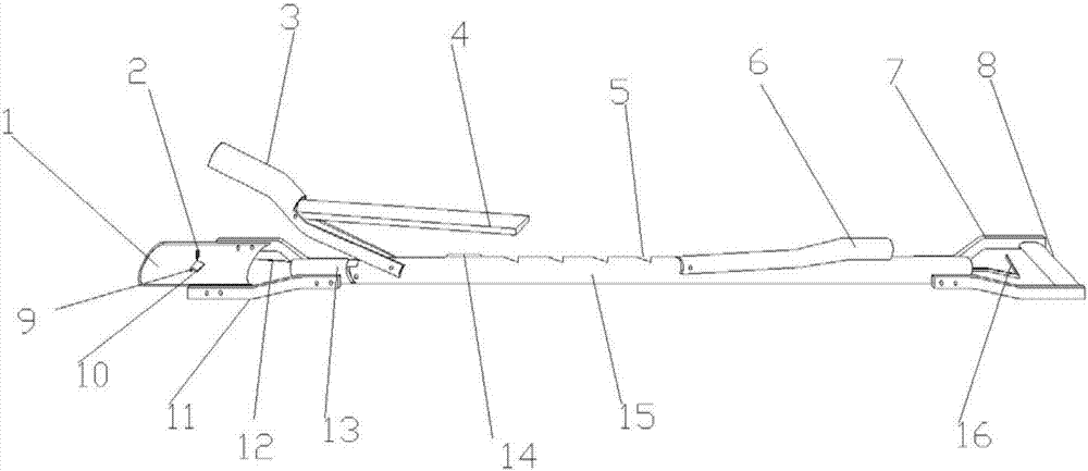
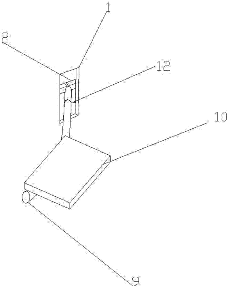
[0017] Such as Figure 1-Figure 2 As shown, an electric drill extension rod includes a first handle 8, a first connecting rod 15 and a first support 1, and the two ends of the first handle 8 are symmetrically provided with handle brackets 7, and the handle brackets 7 are respectively connected to On both sides of the right end of the first connecting rod 15, a switch 16 is provided at the right end of the first connecting rod 15, and the switch 16 is embedded in the inner cavity of the first connecting rod 15. There is a second handle 6, the left side of the second handle 6 is provided with a card slot 5, the left side of the card slot 5 is provided with a second su...


PUM


Abstract

An extension rod for an electric drill according to the present invention includes a first handle, a first connecting rod and a first support, handle brackets are symmetrically arranged at both ends of the first handle, and the handle brackets are respectively connected to the first On both sides of the right end of the connecting rod, a switch is provided at the right end of the first connecting rod, the switch is embedded in the inner cavity of the first connecting rod, a second handle is provided on the first connecting rod, and the second handle A card slot is provided on the left side, and a second support is provided on the left side of the card slot, and the card slot and the second support are both provided on the first connecting rod, and on the second support A fixed bracket is provided, and one end of the first connecting rod is connected with a second connecting rod, and support brackets are arranged symmetrically on both sides of the second connecting rod, and the support brackets are placed on both sides of the first support, and the The first support is connected between the support brackets, which expands the use range of the hand-held electric drill and can better complete drilling operations at high places and at the bottom of deep pits.

Description

technical field [0001] The invention relates to an electric drill extension rod, which belongs to the field of construction machinery appliances. Background technique [0002] The use of electric hand drills can be seen everywhere in construction and decoration industries. When the drilling is at a higher level or at the bottom of a deep pit, you have to use a climbing ladder or build a scaffold, or the drilling work cannot be completed. For simple drilling operations Increase the extra workload and increase the safety hazards of the staff in the drilling operation, especially when the drilling range is large. At a certain height, workers can reach the area that needs to be operated by holding an electric drill or using a climbing tool, but some operating areas are too high, or they do not carry climbing tools in the field, which limits the scope of use of the handheld electric drill, so , needs further improvement. Contents of the invention [0003] The technical proble...

Claims


Application Information

Patent Timeline
Patent Type & Authority Applications(China)
IPC IPC(8): B23B45/14
Inventor 于忠元
Owner AI CAN SEIK MACHINERY EQUIP JIANGSU CO LTD
Why Eureka
Eureka Blog
Learn More