Mounting for a tidal turbine

A technology of turbines and towers, applied in the direction of mechanical equipment, engine components, engine manufacturing, etc., can solve problems such as distortion, power output failure, severe

Inactive Publication Date: 2018-01-02
TIDAL ENERGY
View PDF5 Cites 0 Cited by
  • Summary
  • Abstract
  • Description
  • Claims
  • Application Information

AI Technical Summary

Problems solved by technology

If the power connection goes through the mount to the male part, the cable is protected but twisted even worse, with the potential for power output failure which would require diver repairs, negating the benefit of a detachable turbine
[0005] Second, the female receptacle portion can be difficult to manufacture and itself requires maintenance

Method used


Image

  • Mounting for a tidal turbine
  • Mounting for a tidal turbine
  • Mounting for a tidal turbine

Examples


Embodiment Construction

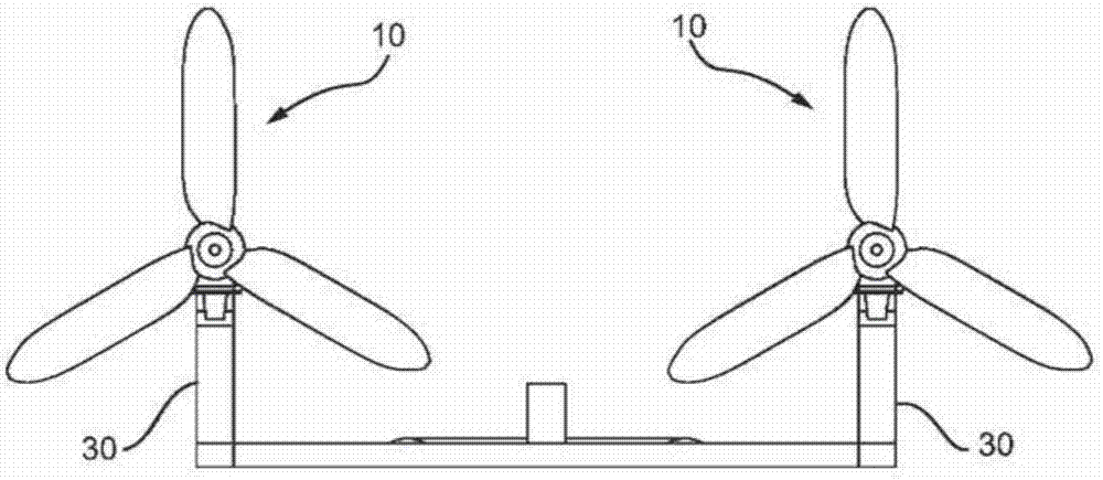
[0019] exist figure 1 , the tidal turbine 10 is mounted on a tower 30 . Power is transmitted from each tower 30 to shore by means of appropriate cables. The electrical connection between each tidal turbine 10 and the electrical output cables leading to the shore is part of the present invention and is referred to below in particular Figure 5 to describe.

[0020] Each tower 30 (which may be a single tower or more part of a larger assembly) is lowered to the sea floor with or without the tidal turbine 10 attached. As described below, if the tower 30 is lowered without the turbine 10 installed, the turbine 10 may then be lowered and separately fitted to the tower 30 .

[0021] Prior to the present invention, if maintenance was required on one of the turbines, the entire structural tower involved had to be lifted from the seabed again using a jack block attached to the eyelet or a diver had to be dispatched to service it; either option Both are expensive, and using the pres...


PUM


Abstract

A marine turbine and tower combination in which the turbine is mountable on the tower. The turbine has a co-operating member to interact with the tower to enable the turbine to be mounted on the towerin a pre-determined alignment. In one arrangement, the support tower comprises a substantially horizontal thruster plate mounted on top of the tower. The thruster has a central aperture to receive adownwardly directed stud on the turbine the thruster plate providing lateral support for the turbine. The stud has a vertical reaction interface around a lower part of the stud which is supported vertically by a reaction ring mounted on the tower.

Description

Background technique [0001] Tidal turbines are an increasingly attractive option for generating electricity. They have two distinct advantages over other so-called alternative energy sources: they are installed underwater and do not cause the same environmental problems as wind turbines, and the tides themselves are completely predictable, and if the turbines are in the right place, Tidal turbines can reliably generate large amounts of electricity. [0002] However, tidal turbines have their own problems, not least the need for maintenance; divers often have to be hired to carry out any inspections and necessary repairs that are needed, which is expensive and inconvenient. Different solutions have been proposed which involve decoupling the turbine and its surrounding nacelle from its mounting on the seabed, lifting the turbine and nacelle using an offshore crane, and transporting it to shore. Most solutions allow the turbine to be placed in one of two or more fixed positions...

Claims


Application Information

Patent Timeline
IPC IPC(8): F03B13/26
CPCF05B2230/604F05B2230/608F05B2240/97F05B2250/292F03B13/264Y02P70/50Y02E10/30Y02E10/20
Inventor 克莱夫·阿谢德彼得·布罗姆利保罗·埃尔金顿
Owner TIDAL ENERGY
Why Eureka
Try Eureka