


Quick Research
Generate reliable direction feasibility study reports for your R&D in just a few steps.

Technical Q&A
Discover and master advanced knowledge NOW. Basics, ideas, possibilities, all at once.

Find Solutions
As an expert in R&D theories, this can generate solutions to your technical problems instantly.

Evaluate Feasibility
Analyze your overall solution with one click, know your potential R&D risks in advance.

Monitor Landscape
Get weekly tech updates, stay abreast of the latest tech innovations and key insights.
On-vehicle display device
A technology for display devices and vehicles, which is applied to projection devices, vehicle components, and image reproducers using projection devices, etc., can solve the problem that users are difficult to notice the timing of linkage, the reduction of vehicle information reportability, and the reduction of vehicle information effectiveness. question
- Summary
- Abstract
- Description
- Claims
- Application Information
AI Technical Summary
Problems solved by technology
Method used
Image

Examples
no. 1 approach
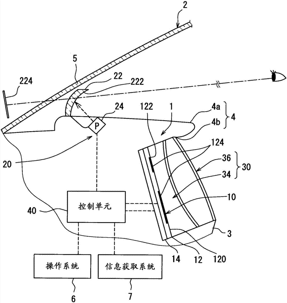
[0041] Such as figure 1 As shown, the display device 1 for a vehicle is mounted in front of a driver's seat in a vehicle 2 . The vehicle display device 1 displays vehicle information related to the vehicle 2 so that a user sitting in the driver's seat can visually recognize it. The vehicle display device 1 has a first display unit 10 , a second display unit 20 , a light emitting unit 30 , and a control unit 40 . In addition, in the following description, upward, downward, and sideways refer to upward, downward, and lateral sides in the vehicle 2 on a horizontal plane, respectively.
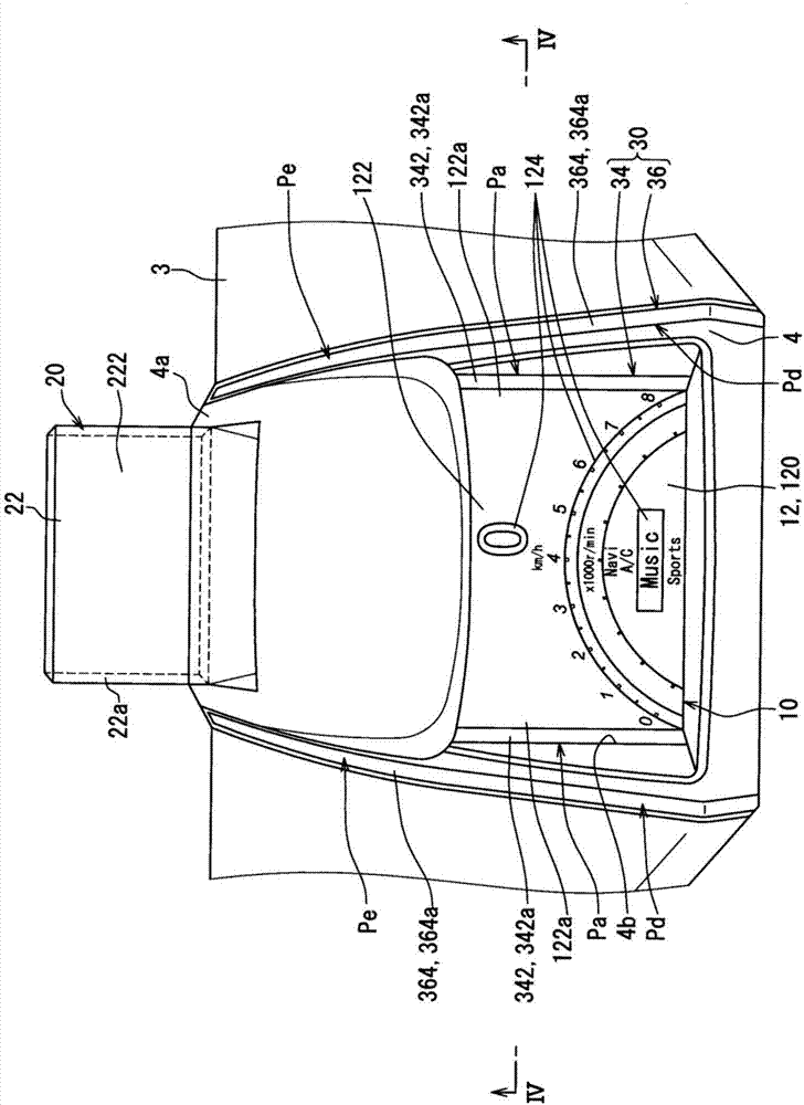
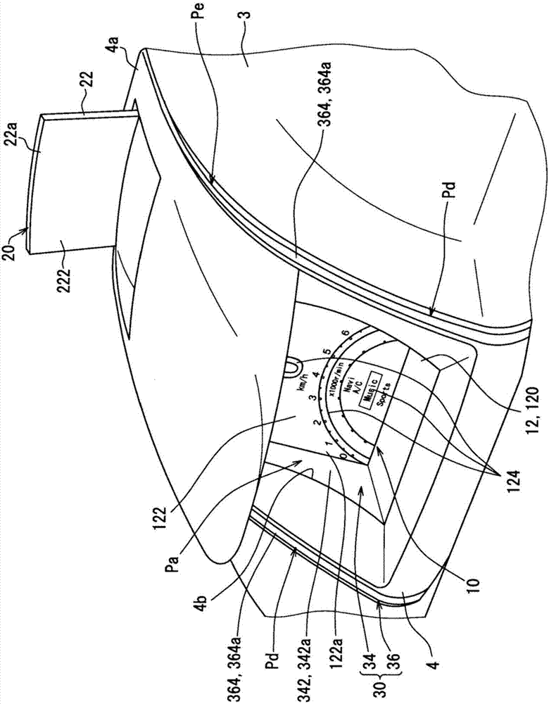
[0042] Such as Figure 1~4 As shown, the first display unit 10 is housed in a hood 4 formed on the instrument panel 3 in front of the driver's seat in the vehicle 2 . The first display unit 10 has a display panel 12 made of, for example, a liquid crystal panel or an organic EL panel. In the display panel 12 , a substantially rectangular first display portion 122 is formed on the inside of the ...
no. 2 approach
[0107] The second embodiment is a modified example of the first embodiment. In the guidance operation mode Md of the second embodiment, the control unit 40 controls each of the adjacent light sources 340 and each of the separated light sources 360, such as Figure 20 In the figure (a), (b), (c), (d), (e), (f), (g) shown in order, each light emitting area 2346, 2366 is changed.
[0108] Specifically, in each adjacent light guide body 342 , the size of the adjacent light emitting region 2346 gradually increases and then gradually decreases in the guiding direction Dd from the first display portion 122 side to the second display portion 222 side. At this time, especially in each adjacent light guide body 342, the size of the adjacent light emitting region 2346 is changed from the adjacent position Pa Figure 20 The lower end of (a) to Figure 20 The upper end of (c) temporarily increases. And in each subsequent adjacent light guide body 342, corresponding to the expansion of t...
PUM
 Abstract
Description
Claims
Application Information
 - R&D Engineer
- R&D Manager
- IP Professional
- Industry Leading Data Capabilities
- Powerful AI technology
- Patent DNA Extraction
Browse by: Latest US Patents, China's latest patents, Technical Efficacy Thesaurus, Application Domain, Technology Topic, Popular Technical Reports.
© 2024 PatSnap. All rights reserved.Legal|Privacy policy|Modern Slavery Act Transparency Statement|Sitemap|About US| Contact US: help@patsnap.com