
Equipment cabinet for outdoor use

A cabinet and outdoor technology, which is applied in the direction of cabinet/cabinet/drawer components, electrical equipment casing/cabinet/drawer, support structure of photovoltaic modules, etc., which can solve the problem of automatic change of placement angle and poor anti-shock effect of the casing , poor reliability of power supply and other issues, to achieve the effect of improving work efficiency, preventing electric shock, and ensuring sufficient power

Inactive Publication Date: 2017-12-26
重庆市荣昌区索领网络科技有限公司
View PDF5 Cites 4 Cited by
  • Summary
  • Abstract
  • Description
  • Claims
  • Application Information

AI Technical Summary

Problems solved by technology

[0002] At present, in the field of communication equipment, outdoor cabinets will become a development trend as a fast and economical networking method; at this stage, outdoor cabinets are mostly deployed in outdoor environments such as roofs, mountains, roadsides, and villages, making outdoor cabinets Facing the problem of poor power supply reliability, the existing outdoor cabinets are equipped with a solar panel on the top to supply the basic daily electricity of the outdoor cabinets, but the traditional solar panels installed on the outdoor cabinets are all fixed , the placement angle cannot be automatically changed according to the specific sunshine conditions, resulting in the problem of low working efficiency of solar panels, resulting in insufficient power in outdoor cabinets, and the existing outdoor cabinet shells have poor anti-shock effects

Method used


Image

  • Equipment cabinet for outdoor use
  • Equipment cabinet for outdoor use
  • Equipment cabinet for outdoor use

Examples


Embodiment Construction

[0015] The following will clearly and completely describe the technical solutions in the embodiments of the present invention with reference to the accompanying drawings in the embodiments of the present invention. Obviously, the described embodiments are only some, not all, embodiments of the present invention. Based on the embodiments of the present invention, all other embodiments obtained by persons of ordinary skill in the art without making creative efforts belong to the protection scope of the present invention.

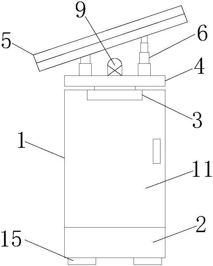
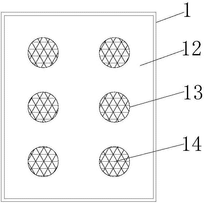
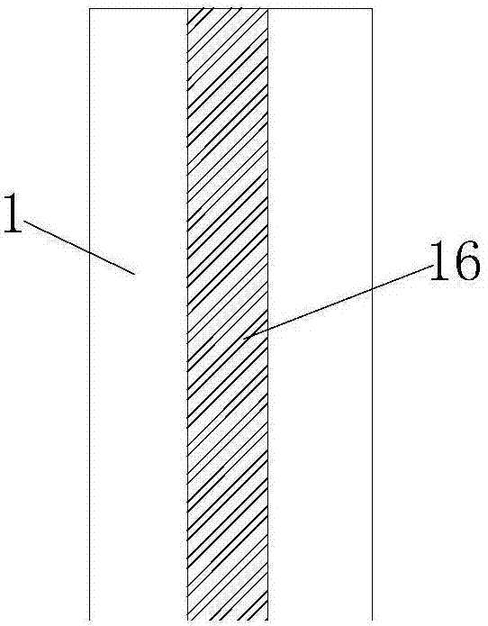
[0016] see Figure 1-4 , the present invention provides a technical solution: a cabinet for outdoor use, including a cabinet body 1, a gap is left in the shell of the cabinet body 1, an insulating layer 16 is arranged inside the gap, and a plastic plate is arranged inside the insulating layer 16 , so that the shell of the outdoor cabinet has a good anti-shock effect, the bottom of the cabinet body 1 is provided with a base 2, the bottom of the base 2 is provid...


PUM


Abstract

The invention discloses an equipment cabinet for outdoor use. The equipment cabinet comprises an equipment cabinet body, a bottom part of the equipment cabinet body is provided with a pedestal, a top part of the equipment cabinet body is provided with a driving motor, a rotating disc is arranged right above the driving motor, an output shaft of the driving motor is fixedly connected with a bottom part of the rotating disc, a solar panel is arranged right above the rotating disc, a bottom part of the solar panel is fixedly connected with the rotating disc via an electric telescopic rod, an upper surface of the solar panel is provided with an ambient light sensor, a controller is arranged in the equipment cabinet body, an upper surface of the rotating disc is provided with an inverter, and an output end of the ambient light sensor is electrically connected with an input end of the controller. Under control of a control system, the equipment cabinet for outdoor use can automatically change an arrangement angle of the solar panel according to specific sunlight conditions, work efficiency of the solar panel can be improved, sufficient electric power can be ensured for the equipment cabinet for outdoor use, and an outer shell of the equipment cabinet for outdoor use is enabled to have great anti-electric shock effects.

Description

technical field [0001] The invention relates to the technical field of communication equipment, in particular to an outdoor cabinet. Background technique [0002] At present, in the field of communication equipment, outdoor cabinets will become a development trend as a fast and economical networking method; at this stage, outdoor cabinets are mostly deployed in outdoor environments such as roofs, mountains, roadsides, and villages, making outdoor cabinets Facing the problem of poor power supply reliability, the existing outdoor cabinets are equipped with a solar panel on the top to supply the basic daily electricity of the outdoor cabinets, but the traditional solar panels installed on the outdoor cabinets are all fixed , the placement angle that cannot be automatically changed according to the specific sunshine conditions causes the problem of low working efficiency of the solar panels, and the phenomenon of power shortage in the outdoor cabinet, and the shell of the existi...

Claims


Application Information

Patent Timeline
IPC IPC(8): H05K5/02H02S20/30F24J2/54
CPCF24S30/422H02S20/30H05K5/0213Y02E10/47Y02E10/50
Inventor 肖洋
Owner 重庆市荣昌区索领网络科技有限公司
Learn More