
Multilayer refractive system imaging model construction method based on light field model

A technology of imaging model and construction method, applied in the field of computer vision, to achieve the effect of intuition and high precision in the process of light propagation

Active Publication Date: 2017-12-22
HUST WUXI RES INST
View PDF2 Cites 11 Cited by
  • Summary
  • Abstract
  • Description
  • Claims
  • Application Information

AI Technical Summary

Problems solved by technology

[0003] The purpose of the present invention is to solve the problems mentioned in the above background technology section by a method for constructing an imaging model of a multi-layer refraction system based on a light field model

Method used


Image

  • Multilayer refractive system imaging model construction method based on light field model
  • Multilayer refractive system imaging model construction method based on light field model
  • Multilayer refractive system imaging model construction method based on light field model

Examples


Embodiment Construction

[0040] The present invention will be further described below in conjunction with drawings and embodiments. It should be understood that the specific embodiments described here are only used to explain the present invention, but not to limit the present invention. In addition, it should be noted that, for the convenience of description, only some parts related to the present invention are shown in the accompanying drawings but not the whole content. Unless otherwise defined, all technical and scientific terms used herein are related to the technical field of the present invention. The skilled person generally understands the same meaning. The terms used herein are for describing specific embodiments only, and are not intended to limit the present invention.

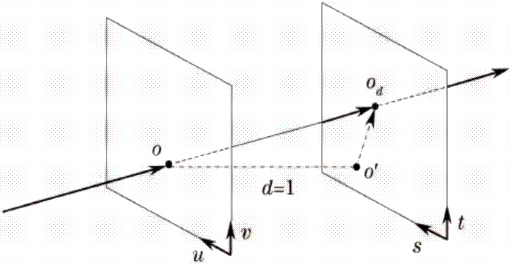
[0041] The following first explains the related knowledge of the light field. The propagation of light in space can use the four-dimensional light field function (u vs t) T express. like figure 1 As shown, the first pl...


PUM


Abstract

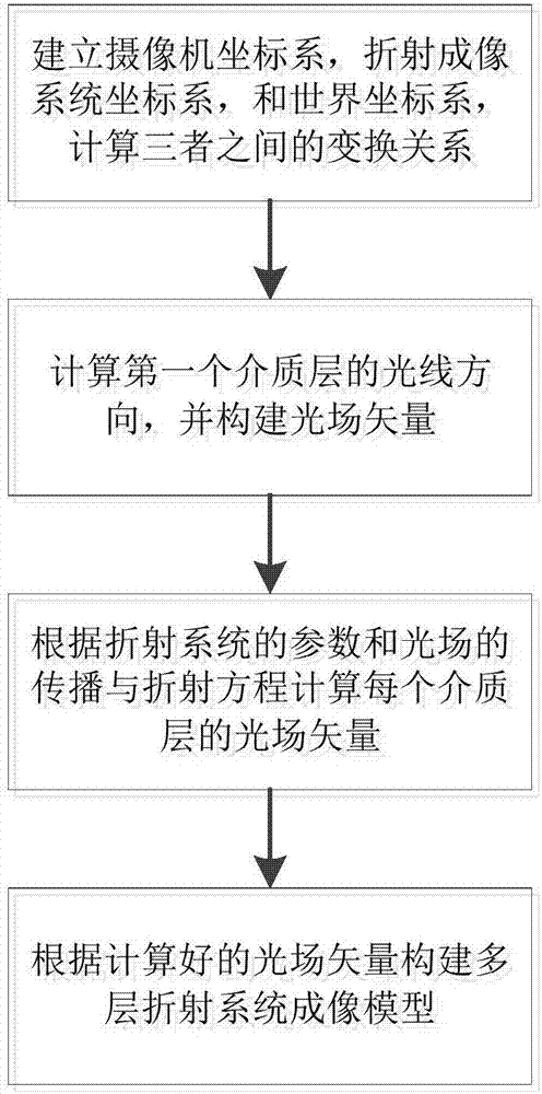
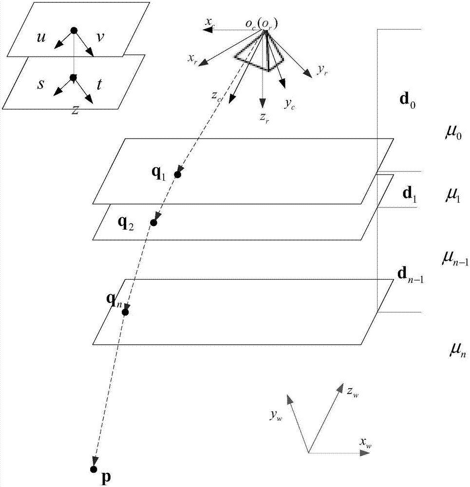
The invention discloses a multilayer refractive system imaging model construction method based on a light field model. The multilayer refractive system imaging model construction method comprises the steps of: S101, constructing a coordinate system of a multilayer refractive model, and constructing a camera coordinate system o<c>x<c>y<c>z<c>, a refractive system imaging coordinate system o<r>x<r>y<r>z<r> and a world coordinate system o<w>x<w>y<w>z<w>; S102, constructing light field vectors according to coordinates of an image point, calculating light field vectors of each dielectric layer according to reflection parameters of the refractive system and a propagation and refraction equation of a light field; S103, and constructing an imaging model of the multilayer refractive system according to the calculated light field vectors of each dielectric layer. The multilayer refractive system imaging model construction method is based on the multilayer refractive model and the light field model, the light field model contains position information of light rays and contains direction information, the light path propagation and refraction equation based on the light field model is given, and the multilayer refractive system imaging model construction method can be used for underwater camera imaging description and imaging description of all cameras additionally provided with protective glass or a filter.

Description

technical field [0001] The invention relates to the field of computer vision, in particular to a method for constructing an imaging model of a multilayer refraction system based on a light field model. Background technique [0002] In the underwater environment, the imaging light will pass through the three layers of refraction media: water, filter, and air. Existing methods often apply the traditional camera model to this refraction system, and use radial distortion coefficients to correct the deviation caused by refraction. However, the effect of refraction on the deviation of different pixels is different, and the use of traditional camera models will produce obvious errors. Contents of the invention [0003] The purpose of the present invention is to solve the problems mentioned above in the background technology section through a method for constructing an imaging model of a multi-layer refraction system based on a light field model. [0004] For reaching this purpo...

Claims


Application Information

Patent Timeline
Patent Type & Authority Applications(China)
IPC IPC(8): G06T7/73G02B27/00
CPCG02B27/0012G06T7/75
Inventor 张旭朱禹轲朱利民
Owner HUST WUXI RES INST
Learn More