Automatic material split packaging equipment
An automatic, sub-packaging technology, applied in packaging, solid materials, transportation and packaging, etc., can solve the problems of uneven impact force, unevenness, inaccurate packaging weight, etc., and achieve the effect of uniform impact force and accurate weighing
- Summary
- Abstract
- Description
- Claims
- Application Information
AI Technical Summary
Problems solved by technology
Method used
Image

Examples
Embodiment 1
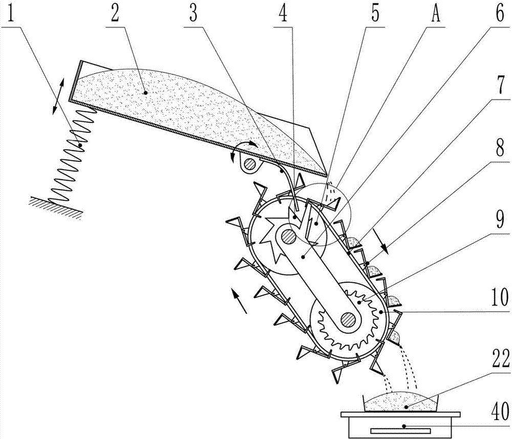
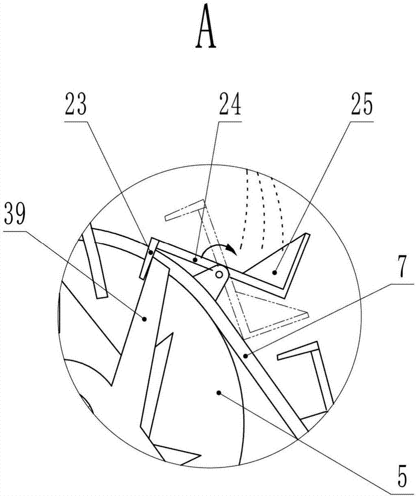
[0017] In embodiment 1, such as figure 1 , 2 Shown, the present invention comprises frame body, lower hopper 2, bucket conveyor and weighing assembly. In order to facilitate the display of the internal structure, the frame structure has been partially omitted in the figure, and only the part connected to other structures is drawn, that is, the straight line with hatching in the figure (except for the section line). The frame structure is used to support, connect and fix other structures. Since the specific structure of the frame is determined by the position and size of other structures and has no impact on the working principle of the present invention, its specific structure will not be repeated.
[0018] The rear end of the lower hopper 2 is open, and the rear end of the lower hopper 2 is hinged with the frame body. On the lower hopper 2, the lower end is fixed on the frame body. When there are more materials in the lower hopper 2, the feeding speed is faster, and the co...
Embodiment 2
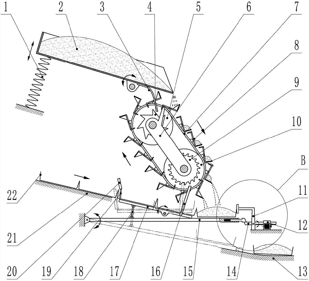
[0024] In embodiment 2, such as image 3 , 4 As shown, the present embodiment includes a frame body, a lower hopper 2, a bucket conveyor and a weighing assembly. Wherein the lower hopper 2, the bucket conveyor and their auxiliary structures and connection relationship are the same as those in Embodiment 1, and will not be repeated in this embodiment. The frame structure is adaptively changed according to the change of the structure of the weighing assembly. The difference between this embodiment and Embodiment 1 mainly lies in the change of the weighing assembly.
[0025]The weighing assembly is located below the bucket conveyor and includes No. 1 rack 21 , No. 2 rack 13 , No. 1 crossbeam 17 , No. 2 crossbeam 15 and No. 3 crossbeam 14 . The No. 1 disc rack 21 and the No. 2 disc rack 13 are fixed on the rack body (or part of the rack body). The No. 1 rack 21, the No. 2 rack 13 and the No. 1 beam 17 are placed obliquely, the front is high and the rear is low. The No. 1 rack ...
Embodiment 3
[0030] In embodiment 3, such as Figure 5 As shown, the present embodiment includes a frame body, a lower hopper 2, a bucket conveyor and a weighing assembly. Wherein the lower hopper 2, the bucket conveyor and their auxiliary structures and connection relationship are the same as those in Embodiment 1, and will not be repeated in this embodiment. The frame structure is adaptively changed according to the change of the structure of the weighing assembly. The difference between this embodiment and Embodiment 1 mainly lies in the change of the weighing assembly.
[0031] The weighing assembly includes No. 1 rack 21, No. 2 rack 13, No. 3 beam 14 and No. 4 beam 30, wherein No. 1 rack 21, No. 2 rack 13 and No. 3 beam 14 and No. 3 crossbeam 14's subsidiary structure and connection relation are the same as embodiment 2, and present embodiment no longer repeats. Described No. 4 crossbeam 30 intermediate positions are hinged with the frame body, wherein the hinge is provided with a ...
PUM
 Abstract
Description
Claims
Application Information
 - Generate Ideas
- Intellectual Property
- Life Sciences
- Materials
- Tech Scout
- Unparalleled Data Quality
- Higher Quality Content
- 60% Fewer Hallucinations
Browse by: Latest US Patents, China's latest patents, Technical Efficacy Thesaurus, Application Domain, Technology Topic, Popular Technical Reports.
© 2025 PatSnap. All rights reserved.Legal|Privacy policy|Modern Slavery Act Transparency Statement|Sitemap|About US| Contact US: help@patsnap.com