An electric card punching machine

A punching machine, electric technology, applied in metal processing and other directions, can solve problems such as safety accidents, fatigue wear, permanent deformation, etc.

Active Publication Date: 2020-08-25
永嘉县恒通制卡设备有限公司
View PDF6 Cites 1 Cited by
  • Summary
  • Abstract
  • Description
  • Claims
  • Application Information

AI Technical Summary

Problems solved by technology

[0006] First, set the cam directly on the motor. Because the motor rotates too fast, the output shaft on the motor needs to complete a round trip within one circle, and the working accuracy is too high.
[0007] Second, the spring reset setting, because the spring is an elastic material, its working principle is completed by its own deformation, so the deformation of the spring back and forth will lead to a series of problems such as permanent deformation, fracture, fatigue wear, etc., and eventually cause the spring to fail. Once the spring fails, the connecting rod will be away from the rotating block under the action of the cam and cannot be reset. What is more serious, the cam will transmit energy to the connecting rod due to the excessive speed of the cam, so that the connecting rod will fly out together with the punching head , resulting in a safety accident

Method used


Image

  • An electric card punching machine
  • An electric card punching machine
  • An electric card punching machine

Examples


Embodiment Construction

[0031] In order to make the object, technical solution and advantages of the present invention clearer, the present invention will be further described in detail below in conjunction with the accompanying drawings.

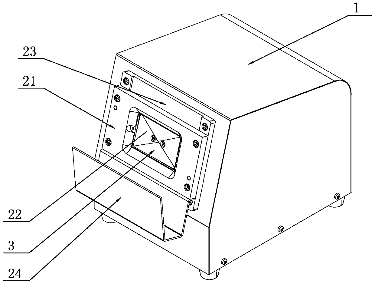
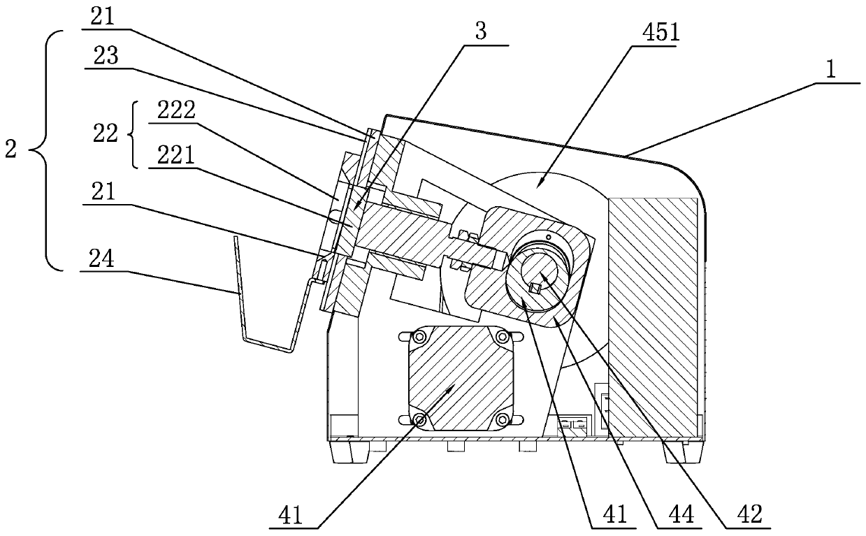
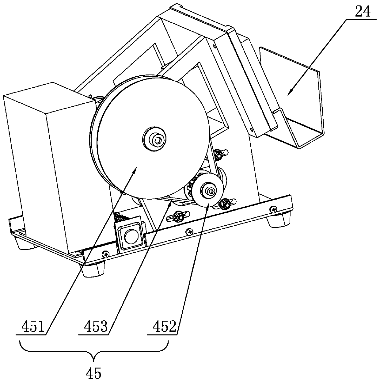
[0032] Such as Figure 1-Figure 8 As shown, the present invention discloses an electric card punching machine, which includes a housing 1, a card window 2 arranged on the housing 1, a punching cutter head 3 arranged in the housing 1, and a power output for moving the punching cutter head 3 Mechanism 4, the power output mechanism 4 includes a motor 41, a rotating shaft 42 rotated by the motor 41 and a cam 43 installed on the rotating shaft 42, the power output mechanism 4 also includes a connecting block 44, and one end of the connecting block 44 is set in linkage with the punching cutter head 3 , the other end is provided with a cam cavity 441 for installation of the cam 43, the outer peripheral surface of the cam 43 is against the inner peripheral surface of the ...


PUM


Abstract

The invention relates to an electric card punching machine which comprises a housing, a card making window, a punching cutter head and a power output mechanism for moving the punching cutter head; the power output mechanism comprises a motor, a rotating shaft rotating through the motor, and a cam arranged on the rotating shaft; the power output mechanism further comprises a connecting block; one end of the connecting block is linked with the punching cutter head; a cam cavity in which the cam is arranged is formed in the other end of the connecting block; the external periphery surface of the cam abuts against the internal periphery surface of the cam cavity of the connecting block; a first division plane is arranged on the side, on which the cam faces towards the punching cutter head, of the cam cavity; a second division plane is arranged is on the side, on which the cam departs from the punching cutter head, of the cam cavity; when the cam abuts against the first division plane and has a trend to rotate towards the first division plane, the connecting block drives the punching cutter head to move towards the card making window; and when the cam abuts against the second division plane and has a trend to rotate towards the second division plane, the connecting block drives the punching cutter head to move to be far from the card making window. With the adoption of the scheme, the electric card punching machine can be automatically reset and is high in safety performance.

Description

technical field [0001] The invention relates to an electric card punching machine. Background technique [0002] Cards are used in various occasions, such as ID cards, VIP cards, telephone cards, etc., so the research on card mechanization has developed rapidly. [0003] The electric card punching machine usually includes a shell, a card window, a punching cutter head and a power output mechanism. The card is adapted, the punching head is driven by the power output mechanism, moves inside the casing and penetrates to the outside of the casing, the card making window is set on the casing, and is located at the place where the punching head penetrates the casing There is a window, and the shape and size of the window are adapted to the place where the punching cutter head runs through the shell. The card material is put in through the card making window, and the part that needs to be cut is placed in the window; the power output mechanism is activated to make the punching he...

Claims


Application Information

Patent Timeline
Patent Type & Authority Patents(China)
IPC IPC(8): B26F1/40B26D5/16B26D7/32
CPCB26D5/16B26D7/32B26F1/40
Inventor 赵晓青
Owner 永嘉县恒通制卡设备有限公司
Why Eureka
Try Eureka