
Waterproof lightweight type pulling rod case

A trolley case, lightweight technology, applied to luggage, clothing, accessories, etc., can solve the problems of sewage soaking the case body, laborious and other problems, and achieve the effect of reducing the difficulty of lifting

Inactive Publication Date: 2017-12-22
胡振华
View PDF6 Cites 0 Cited by
  • Summary
  • Abstract
  • Description
  • Claims
  • Application Information

AI Technical Summary

Problems solved by technology

[0002] The trolley suitcase is a basic travel item, equipped with a trolley and rollers; since the height of the rollers is fixed, during the towing process, if there is water on the road, it is usually impossible to use the rollers for towing, otherwise the sewage will be very serious It is possible to soak the box body; on the other hand, when the current trolley case goes up the steps, at least the force equal to the weight of the trolley case is needed to lift the case body. more difficult

Method used


Image

  • Waterproof lightweight type pulling rod case
  • Waterproof lightweight type pulling rod case
  • Waterproof lightweight type pulling rod case

Examples


Embodiment 1

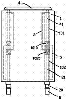
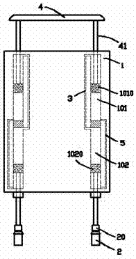
[0014] exist figure 1 , figure 2 In the first embodiment shown, the waterproof portable trolley case includes a box body 1; the front and rear rollers (not shown) and the rear row rollers 2 are respectively provided on the front and rear sides below the box body 1; the inside of the box body 1 A left-right symmetrical longitudinal cylinder is arranged on the rear side; the middle part of the longitudinal cylinder is partitioned to form an upper cylinder 101 and a lower cylinder 102, and the uppermost end of the upper cylinder 101 communicates with the uppermost end of the lower cylinder 102 through the first air pipe 3 , the lowermost end of the upper cylinder 101 communicates with the lowermost end of the lower cylinder 102 through the second air pipe 5; the upper wheel seat 20 of the rear row of rollers 2 is connected to the upwardly extending wheel rod 21, and the wheel rod 21 stretches into the lower cylinder 102, and can slide up and down along the axis of the lower cyl...

Embodiment 2

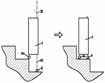
[0018] for image 3 In the second embodiment shown, the pull rod 41 is detachably connected to the upper sliding plug 1010; when the rear roller 2 is not required to extend downward, the pull rod 41 can be separated from the upper sliding plug 1010. In the process of pulling the pull rod 41 upwards, the upper sliding plug 1010 and the lower sliding plug 1020 remain motionless, which does not affect the position of the rear rollers 2 . Specifically, the detachable connection is formed by a longitudinal stud 411 fixed at the lower end of the pull rod 41 and a longitudinal screw hole 412 on the upper side of the upper sliding plug 1010, and the pull rod 41 can freely rotate around its own axis, so that travelers By manually screwing the pull rod 41, the pull rod 41 is axially connected or disassembled with the upper slide plug 1010; Provides lateral restraint and prevents tie rod 41 from being pulled upwards out of upper cylinder 101 .


PUM


Abstract

The present invention provides a waterproof lightweight type pulling rod case, which comprises a box, wherein a front row of rollers and a rear row of rollers are respectively arranged on the front side and the rear side below the box, the interior close to the rear side inside the box is provided with vertical gas cylinders symmetrically arranged on the left and the right, the middle portion of the gas cylinder is separated to form an upper portion gas cylinder and a lower portion gas cylinder, the uppermost end and the lowermost end of the upper portion gas cylinder are communicated to the uppermost end and the lowermost end of the lower portion gas cylinder respectively through a first gas pipe and a second gas pipe, the upper portion roller seat of the rear row of the rollers is connected to a wheel rod upwardly extending into the lower portion gas cylinder, an upper sliding plug is arranged in the upper portion gas cylinder and is connected to an upwardly extending pulling rod, a lower sliding plug is positioned at the upper end of the lower portion gas cylinder when the upper sliding plug is positioned at the lower end of the upper portion gas cylinder, and the upper sliding plug and the lower sliding plug always maintain reverse movement. According to the present invention, the pulling rod case can be normally pulled in the case of the water on the road surface, and the assisting function can be provided during the climbing of the steps.

Description

technical field [0001] The invention relates to the field of travel articles, in particular to a trolley case. Background technique [0002] The trolley suitcase is a basic travel item, equipped with a trolley and rollers; since the height of the rollers is fixed, during the towing process, if there is water on the road, it is usually impossible to use the rollers for towing, otherwise the sewage will be very serious It is possible to soak the box body; on the other hand, when the current trolley case goes up the steps, at least the force equal to the weight of the trolley case is needed to lift the case body. more difficult. Contents of the invention [0003] In view of the above problems, the object of the present invention is to provide a waterproof and portable trolley case, which can be normally towed in the case of water on the road, and provides a power assist function in the process of going up the steps. [0004] The technical solution adopted by the present...

Claims


Application Information

Patent Timeline
Patent Type & Authority Applications(China)
IPC IPC(8): A45C13/26A45C13/00A45C13/02A45C5/14
CPCA45C13/262A45C5/14A45C13/008A45C13/021A45C2013/267
Inventor 胡振华
Owner 胡振华
Learn More