A gearbox solenoid valve driving circuit and its control method

A solenoid valve drive and gearbox technology, applied in the field of solenoid valves, can solve problems such as the inability to provide communication interfaces and complex structures of multiple solenoid valves, and achieve the effect of realizing digital control and simplifying control

Inactive Publication Date: 2020-07-28
北京驰亿隆科技有限公司
View PDF8 Cites 0 Cited by
  • Summary
  • Abstract
  • Description
  • Claims
  • Application Information

AI Technical Summary

Problems solved by technology

[0003] Aiming at the defects existing in the prior art, the object of the present invention is to provide a gearbox solenoid valve drive circuit and its control method, which solves the problem that the current solenoid valve drive circuit cannot provide a communication interface, and the structure when multiple solenoid valves cooperate to act complicated question

Method used


Image

  • A gearbox solenoid valve driving circuit and its control method
  • A gearbox solenoid valve driving circuit and its control method

Examples


Embodiment Construction

[0024] The present invention will be described in further detail below in conjunction with the accompanying drawings.

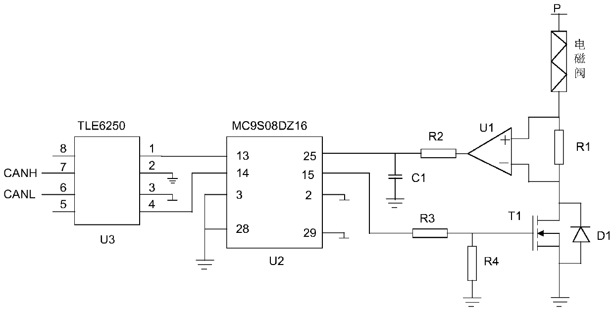
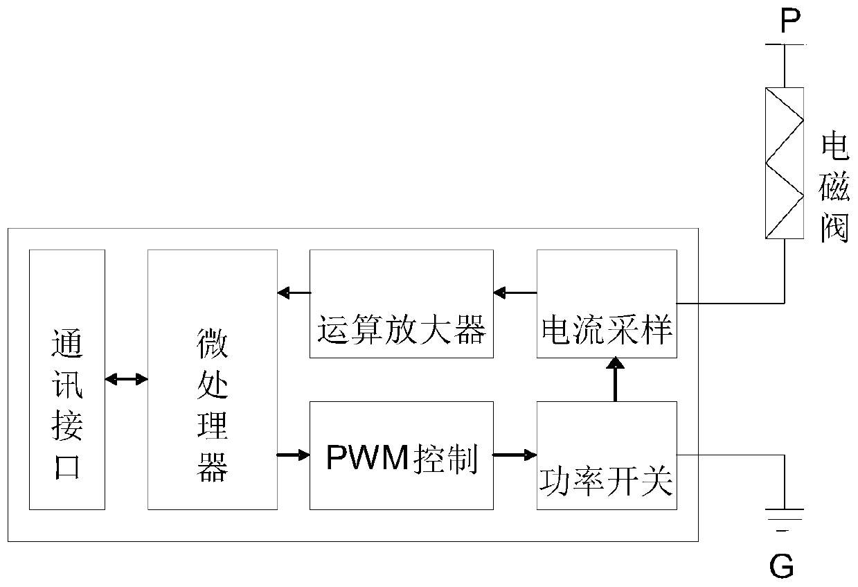
[0025] Such as Figure 1-2 As shown, a gearbox solenoid valve driving circuit includes: a microprocessor chip, a communication interface chip, an operational amplifier U1 and a power switch tube T1;

[0026] The pin 1 of described communication interface chip is connected with the pin 13 of microprocessor chip, the pin 4 of described communication interface chip is connected with the pin 14 of microprocessor chip, the pin 3 of described communication interface chip is connected Power supply, the pin 2 of the communication interface chip is grounded, the pin 6 of the communication interface chip is connected to a low level, and the pin 7 of the communication interface chip is connected to a high level;

[0027] The pin 25 of the microprocessor chip is connected with one end of the capacitor C1, the other end of the capacitor C1 is grounded, the pin 25 of the ...


PUM


Abstract

The invention provides a transmission case electromagnetic valve driving circuit and a control method of a transmission case electromagnetic valve. The transmission case electromagnetic valve driving circuit comprises a microprocessor chip, a communication interface chip, an operational amplifier and a power switch tube. The control method of the transmission case electromagnetic valve comprises the steps that: an external control instruction is connected to the microprocessor chip through the communication interface chip; the external control instruction is transmitted to the microprocessor chip; after the microprocessor chip receives the external control instruction, the microprocessor chip calculates and outputs a PWM signal according to a predetermined driving algorithm, the PWM signal drives the power switch tube, and the driving control of the electromagnetic valve is realized; the current of the electromagnetic valve is collected through a sampling resistor; collected current is processed by the operational amplifier and then is outputted to the microprocessor chip, and the microprocessor chip adjusts the output of the PWM signal according to a current sampling value; and at the same time, the microprocessor chip outputs switch-on and switch-off states of the electromagnetic valve and real-time current value to an external control end through the communication interface chip.

Description

technical field [0001] The invention relates to the technical field of solenoid valves, in particular to a drive circuit and a control method for a gearbox solenoid valve. Background technique [0002] Pulse width modulation solenoid valves are widely used in hydraulic mechanical automatic transmissions. This solenoid valve has the advantages of fast response, strong anti-interference ability and high cost performance. The response speed and action accuracy of the solenoid valve applied in the gearbox system directly affect the shifting performance of the gearbox. In the gearbox system, it is not only required that the solenoid valve should respond quickly when it initially moves, but also requires the solenoid valve to be powered off. Timed deadlines can be responded quickly. In the process of shifting gears, the gearbox requires multiple solenoid valves to cooperate with each other, coordinate and coordinate, and accurately respond to control commands in order to accurate...

Claims


Application Information

Patent Timeline
Patent Type & Authority Patents(China)
IPC IPC(8): G05B19/042F16K31/02
CPCF16K31/02G05B19/0423G05B2219/21151
Inventor 王学禄崔玲杜吉龙张国岳
Owner 北京驰亿隆科技有限公司
Why Eureka
Try Eureka