
A calibration device for a six-degree-of-freedom force and torque sensor

A torque sensor and calibration device technology, applied in the direction of measuring devices, force/torque/power measuring instrument calibration/testing, instruments, etc., can solve problems such as difficult to guarantee, unable to complete sensor measurement, shape restrictions, etc., to achieve fixation and replacement Easy and fast effect

Active Publication Date: 2019-12-03
MOTUS TECHNOLOGIES INC
View PDF7 Cites 0 Cited by
  • Summary
  • Abstract
  • Description
  • Claims
  • Application Information

AI Technical Summary

Problems solved by technology

[0002] The six-component force and moment sensor is an integral sensor used to measure and calculate the force and moment of six degrees of freedom, also referred to as "six-dimensional force sensor". The six-component force and moment sensor has complex loading force sources and The problem of complex testing standards
The existing six-dimensional force sensor calibration device has the following disadvantages: 1), because the measured sensor is placed between the upper platform and the lower platform of the stewart platform, it is very inconvenient to replace the tested part; 2), because The sensor under test is fixed by two upper and lower three-jaw chucks, so the size and shape of the tested part are limited, and it is impossible to complete the measurement of different styles of sensors; 3), this detection method requires two upper and lower three-jaw chucks and the tested It is difficult to ensure that the axes of the three measuring sensors coincide, which will affect the measurement accuracy; 4), 6 unidirectional standard force sensors are installed on the electric push rod, and the calculation is the force and moment applied to the tested part, which is affected The influence of the clearance of the universal joint will also affect the accuracy

Method used


Image

  • A calibration device for a six-degree-of-freedom force and torque sensor
  • A calibration device for a six-degree-of-freedom force and torque sensor
  • A calibration device for a six-degree-of-freedom force and torque sensor

Examples


Embodiment Construction

[0024] The principles and features of the present invention are described below in conjunction with the accompanying drawings, and the examples given are only used to explain the present invention, and are not intended to limit the scope of the present invention.

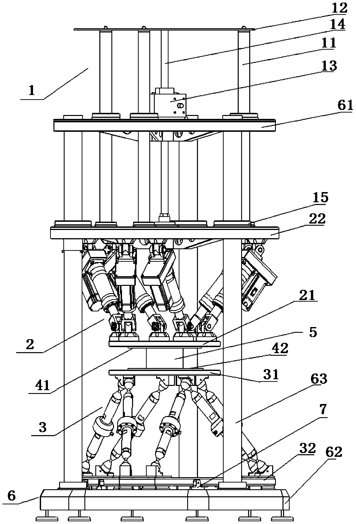
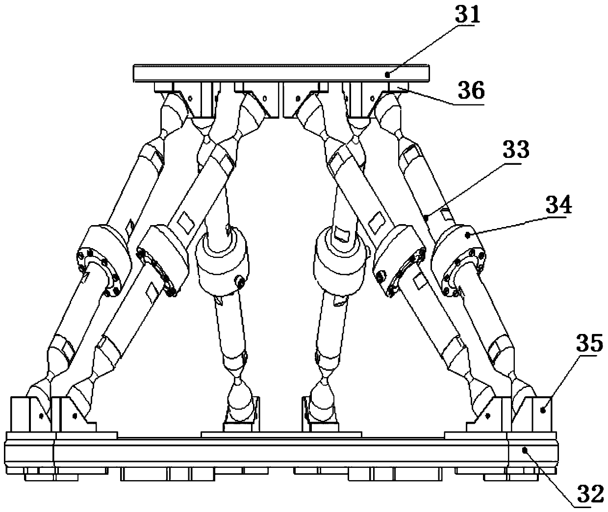
[0025] Such as Figure 1-Figure 5 As shown, a calibration device of a six-degree-of-freedom force and moment sensor, including a lifting mechanism 1, a six-degree-of-freedom motion tooling 2 of a stewart structure, and a six-degree-of-freedom force and moment measurement tooling 3 of a stewart structure, the six-degree-of-freedom motion The tooling 2 is installed upside down on the bottom of the lifting mechanism 1, and can move up and down with the lifting mechanism 1. The six-degree-of-freedom force and moment measuring tooling 3 is located below the six-degree-of-freedom motion tooling 2. The measured six-degree-of-freedom force and moment sensor 5 is fixed between the six-degree-of-freedom motion tooling 2 and t...


PUM


Abstract

The invention relates to a calibration device for a six-degree-of-freedom force and torque sensor. The calibration device comprises a lifting mechanism, a six-degree-of-freedom movement tool of a stewart structure and a six-degree-of-freedom force and torque measurement tool of the stewart structure, wherein the six-degree-of-freedom movement tool is mounted at the bottom of the lifting mechanism in an inverted manner and can move up and down along with the lifting mechanism; the six-degree-of-freedom force and torque measurement tool is positioned below the six-degree-of-freedom movement tool; and the six-degree-of-freedom force and torque sensor to be detected is fixed between the six-degree-of-freedom movement tool and the six-degree-of-freedom force and torque measurement tool. According to the calibration device, mounting, fixing and replacement of the six-degree-of-freedom force and torque sensor to be detected become convenient and quick, the detection accuracy can be improved, and the stability is good.

Description

technical field [0001] The invention relates to a sensor calibration device, in particular to a six-degree-of-freedom force and torque sensor calibration device. Background technique [0002] The six-component force and moment sensor is an integral sensor used to measure and calculate the force and moment of six degrees of freedom, also referred to as "six-dimensional force sensor". The six-component force and moment sensor has complex loading force sources and The detection standard is complex. The structural body of the six-dimensional force sensor calibration device in the prior art solution is a six-degree-of-freedom motion platform with a stewart structure, driven by an electric push rod, which can continuously load arbitrary forces and moments in space, and is installed on the upper platform and the lower platform respectively. There is a three-jaw chuck, the sensor to be tested is fixed in the middle, and standard force sensors are installed on the six electric push ...

Claims


Application Information

Patent Timeline
Patent Type & Authority Patents(China)
IPC IPC(8): G01L25/00
CPCG01L25/00G01L25/003
Inventor 肖文皓肖琴罗文豹李绍安
Owner MOTUS TECHNOLOGIES INC
Learn More