Airflow-impact-accelerated rotational kinetic energy output and power generator drive device

A driving device and generator technology, applied in wind power generation, engines, wind engines, etc., can solve problems such as low torque or speed, insufficient power output efficiency, failure to further fully extract wind and air kinetic energy, etc., to achieve perfect structure, The effect of improving power output efficiency

Pending Publication Date: 2017-12-12
李占江
View PDF8 Cites 1 Cited by
  • Summary
  • Abstract
  • Description
  • Claims
  • Application Information

AI Technical Summary

Problems solved by technology

[0002] At present, although various wind power generation technologies are quite mature, they are not perfect. Their torque or speed is obviously low due to the wind intensity, and the power output efficiency is obviously insufficient, and the aerodynamic energy contained in the wind power has not yet been fully extracted.

Method used


Image

  • Airflow-impact-accelerated rotational kinetic energy output and power generator drive device
  • Airflow-impact-accelerated rotational kinetic energy output and power generator drive device
  • Airflow-impact-accelerated rotational kinetic energy output and power generator drive device

Examples


Embodiment Construction

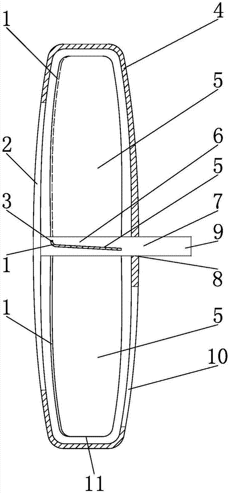
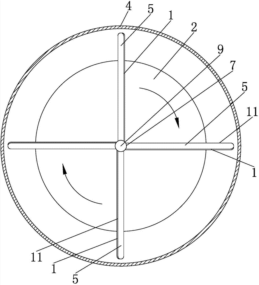
[0010] A kind of airflow impact acceleration rotary kinetic energy output and generator driving device, such as figure 1 As shown, the orthographic projection of the outside of the casing 4 on the radial direction of the internal chamber of the casing 4 and the orthographic projection of the internal chamber of the casing 4 on its own radial direction are generally flat, and the internal chamber of the casing 4 is outside the casing 4. The orthographic projection in the thickness direction is a perfect circle, and the support shaft 7 includes the tail shaft section 6 at its tail end, which is located at the geometric center of the inner chamber of the casing 4 on its own radial direction, and the support shaft 7 includes the head shaft section 9 at its head end. The perforation 8 provided at the geometric center of the shell wall at the head end of the shell 4 in the radial direction of the inner chamber of the shell 4 passes through the shell wall at the head end of the shell ...


PUM


Abstract

The invention relates to a power machine technology, belongs to wind power output equipment, and particularly discloses an airflow-impact-accelerated rotational kinetic energy output and power generator drive device. Wind power blades annularly and uniformly distributed around the central axis parallel to a straight line, where a bearing shaft is located, of the bearing shaft are installed on the bearing shaft; the wind power blades are in transmission connection with the bearing shaft in a manner of revolution; an intake port penetrating through the wall body of a shell wall at the head end of a shell in the outer thickness direction of the shell, communicating with the inner chamber of the shell, and extending in the radial direction of the inner chamber of the shell in the shape of a straight-line segment, is formed in the shell wall, and an exhaust port penetrating through the wall body of the shell wall at the tail end of the shell in the outer thickness direction of the shell is formed in the shell wall; and a tail-end barrel port formed in the tail end of an airflow guide-in acceleration barrel communicates with the intake port, and the inner barrel diameter of the cross section perpendicular to the own length direction of the airflow guide-in acceleration barrel is correspondingly and continuously reduced towards the length direction of the airflow guide-in acceleration barrel from a head-end barrel port to the tail-end barrel port. The airflow-impact-accelerated rotational kinetic energy output and power generator drive device disclosed by the invention is more complete in structure, obviously increases power output efficiency, and further adequately extracts air kinetic energy contained in wind power.

Description

technical field [0001] The invention relates to power machine technology, and belongs to wind power output equipment, in particular to an airflow impact acceleration rotary kinetic energy output and generator driving device. Background technique [0002] At present, although various wind power generation technologies are quite mature, they are not perfect. Their torque or rotational speed is obviously low due to the wind intensity, and the power output efficiency is obviously insufficient, and the aerodynamic energy contained in the wind power has not yet been fully extracted. . Contents of the invention [0003] The purpose of the present invention is to provide a rotational kinetic energy output and generator drive device of airflow impact acceleration type, which has a more complete structure, significantly improves the power output efficiency, and can further fully extract the air kinetic energy contained in the wind force. [0004] The object of the present invention...

Claims


Application Information

Patent Timeline
Patent Type & Authority Applications(China)
IPC IPC(8): F03D9/25F03D1/04F03D1/06
CPCF03D1/04F03D1/065F03D9/25Y02E10/72
Inventor 李占江
Owner 李占江
Why Eureka
Try Eureka