Low-power-consumption comparator circuit

A comparator circuit and low power consumption technology, which is applied in the field of low power comparator circuits, can solve the problems of power consumption of pre-amplification circuits and high power consumption of circuits, so as to reduce power consumption, reduce power consumption, and realize effective functions. The effect of consumption control

Inactive Publication Date: 2017-12-08
SHANGHAI HUAHONG GRACE SEMICON MFG CORP
View PDF5 Cites 5 Cited by
  • Summary
  • Abstract
  • Description
  • Claims
  • Application Information

AI Technical Summary

Problems solved by technology

[0004] However, although this comparator circuit can achieve fast and high-precision comparison, its pre-amplifier circuit (Pre-Amplifier) ​​consumes too much power, resulting in high power consumption of the circuit

Method used


Image

  • Low-power-consumption comparator circuit
  • Low-power-consumption comparator circuit
  • Low-power-consumption comparator circuit

Examples


Embodiment Construction

[0023] The implementation of the present invention is described below through specific examples and in conjunction with the accompanying drawings, and those skilled in the art can easily understand other advantages and effects of the present invention from the content disclosed in this specification. The present invention can also be implemented or applied through other different specific examples, and various modifications and changes can be made to the details in this specification based on different viewpoints and applications without departing from the spirit of the present invention.

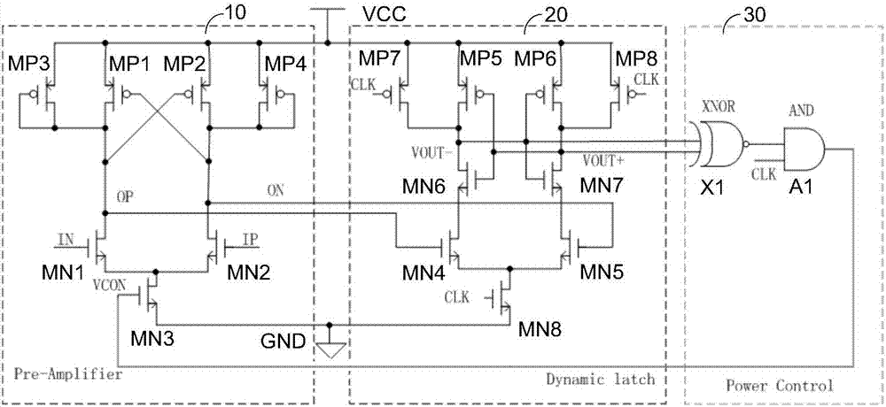
[0024] figure 2 It is a circuit structure diagram of a low power consumption comparator circuit in the present invention. Such as figure 2 As shown, a low-power comparator circuit of the present invention includes: a pre-amplifier circuit (Pre-Amplifier) ​​10, a dynamic latch circuit (Dynamic latch) 20 and a power control circuit (Power Control) 30. Among them, the pre-amplifier circuit...


PUM


Abstract

The invention discloses a low-power-consumption comparator circuit, which comprises a pre-amplifying circuit, a dynamic latch circuit and a power control circuit, wherein the pre-amplifying circuit is used for pre-amplifying an input differential signal IP/IN under the control of a power control signal VCON; the dynamic latch circuit is used for performing dynamic latch on differential output OP/ON of the pre-amplifying circuit under the control of a clock signal CLK; and the power control circuit is used for generating the power control signal VCON according to the output VOUT+/VOUT- of the dynamic latch circuit under the control of the clock signal CLK. The power consumption of the comparator circuit can be reduced according to the invention.

Description

technical field [0001] The invention relates to a circuit, in particular to a low power consumption comparator circuit. Background technique [0002] A comparator is a commonly used module in analog circuits, and is generally widely used in ADC (Analog-to-Digital Converter, analog-to-digital converter), OSC (oscillator, oscillator) and various detection circuits. [0003] In order to achieve fast and high-precision comparison, a common comparator architecture is a combination of pre-amplifier (Pre-Amplifier) ​​and dynamic latch (Dynamic Latch), such as figure 1 As shown, the comparator includes a pre-amplifier circuit 10 and a dynamic latch circuit 20, wherein the pre-amplifier circuit (Pre-Amplifier) ​​10 is composed of NMOS transistors MN1, MN2, MN3 and PMOS transistors MP1, MP2, MP3, MP4. To pre-amplify the input differential signal IP / IN; the dynamic latch circuit (Dynamiclatch) 20 is composed of NMOS transistors MN4, MN5, MN6, MN7, MN8 and PMOS transistors MP5, MP6, MP...

Claims


Application Information

Patent Timeline
Patent Type & Authority Applications(China)
IPC IPC(8): H03K5/24
CPCH03K5/249
Inventor 陈丹凤
Owner SHANGHAI HUAHONG GRACE SEMICON MFG CORP
Why Eureka
Try Eureka