Measuring mechanism of resistance distribution in model test of ship jet drag reduction

A model test, resistance distribution technology, applied in ship construction, ship design, ship components, etc., can solve the problems of large difference, affecting the accuracy of test volume, gas escape and rapid diffusion, etc., to increase stability and improve measurement. Accuracy and reliability, the effect of improving accuracy and reliability

Active Publication Date: 2019-04-05
CHINA SHIP SCIENTIFIC RESEARCH CENTER (THE 702 INSTITUTE OF CHINA SHIPBUILDING INDUSTRY CORPORATION)
View PDF5 Cites 0 Cited by
  • Summary
  • Abstract
  • Description
  • Claims
  • Application Information

AI Technical Summary

Problems solved by technology

Therefore, the small-scale model test method for ship air jet drag reduction has inherent defects, and it is impossible to accurately predict the effect and duration of the actual ship air jet drag reduction based on the model test results. In the large-scale model test, due to the large scale of the model, the Floating, escaping and spreading in water are fast, which affects the accuracy of test measurements
The conventional total resistance measurement method cannot be effectively converted due to the large difference between the boundary conditions of the bubble edge and the real ship. At the same time, the total resistance measurement method cannot simulate the continuous distance of the bubble drag reduction, which is not conducive to the application of the real ship

Method used


Image

  • Measuring mechanism of resistance distribution in model test of ship jet drag reduction
  • Measuring mechanism of resistance distribution in model test of ship jet drag reduction
  • Measuring mechanism of resistance distribution in model test of ship jet drag reduction

Examples


Embodiment Construction

[0030] The specific implementation manner of the present invention will be described below in conjunction with the accompanying drawings.

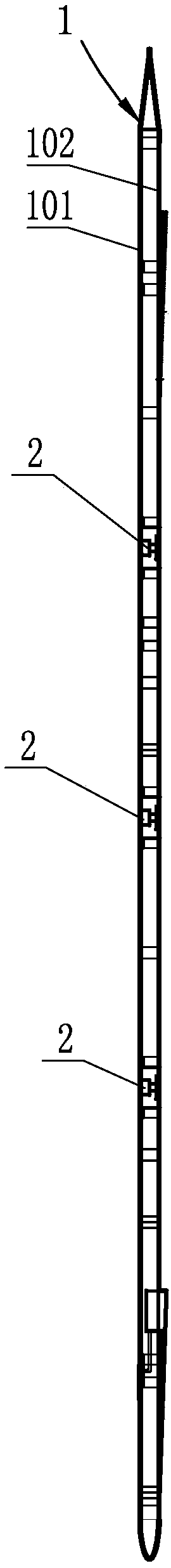
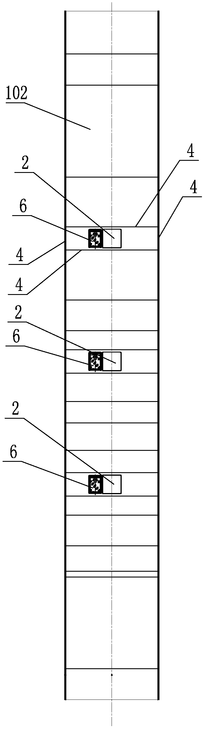
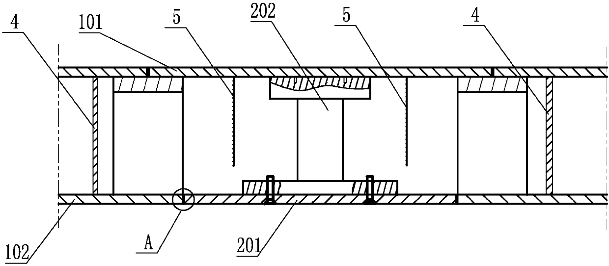
[0031] See figure 1 , figure 2 The resistance distribution measuring mechanism in the ship air jet drag reduction model test of the present invention includes at least three force-measuring units 2 arranged at intervals along the longitudinal direction of the model to be tested 1, and all force-measuring units 2 are distributed at least at the head of the model to be tested 1 in the longitudinal direction. Parts, middles and tails; see image 3 , Figure 4 , the force-measuring unit 2 includes a force-measuring plate 201 and a force-measuring sensor 202 affixed to the top of the force-measuring plate 201. 101 is fixed, and the lower plate 102 of the model to be tested 1 is provided with a through installation groove, the force measuring plate 201 is suspended in the installation groove, and there is an air gap around the force measurin...


PUM


Abstract

A resistance distribution measuring mechanism in a ship jet resistance reduction model experiment comprises at least three force measuring units which are arranged in the longitudinal direction of a to-be-measured model, and all the force measuring units are at least distributed at a head, a middle part and a tail of the longitudinal direction of the to-be-measured model; each force measuring unit comprises a force measuring plate and a force measuring sensor fixedly connected to the force measuring plate; the to-be-measured model is of a double-layer flat plate structure, the upper ends of the force measuring sensors are fixedly connected with an upper layer flat plate of the to-be-measured model, a penetrating mounting groove is formed in a lower layer flat plate of the to-be-measure model, the force measuring plates are arranged in the mounting groove in a suspending mode, and air gaps are left in the periphery of the force measuring plates and the periphery of the mounting groove; baffles are arranged on the periphery of each force measuring unit, the upper ends and the lower ends of the baffles are fixedly connected with the position between the upper layer flat plate and the lower layer flat plate correspondingly in a sealing mode, and force measuring cavities with air gaps are formed by the baffles on the peripheries of the force measuring units, the upper layer flat plate, the lower layer flat plate and the force measuring plates. The resistance distribution measuring mechanism can effectively measure the resistance reduction effects of the positions at different distances from a spraying port under an air injection state and the economic distance of constant resistance reduction of the air, and the measuring result is accurate and reliable.

Description

technical field [0001] The invention relates to the technical field of ship hydrodynamic tests, in particular to an air jet drag reduction model test, in particular to a resistance measuring mechanism in the air jet drag reduction model test. Background technique [0002] The traditional small-scale model air injection drag reduction performance research is mainly obtained by measuring the change of the total resistance of a small-scale flat plate in the air injection state. Feedback from a large number of experimental studies and a small number of real ship results shows that at present, the drag reduction effect obtained by this type of model test method is very different from that of a real ship. The difference is that the motion of the fluid on the surface of the model is not similar to that of a real ship; on the other hand, on a small-scale flat plate, the air bubbles can wrap the flat plate very well without escaping and diffusing out of the flat plate too early. In ...

Claims


Application Information

Patent Timeline
Patent Type & Authority Patents(China)
IPC IPC(8): B63B9/02B63B71/20
CPCB63B71/20
Inventor 黄红波施小勇张传鸿薛庆雨王建芳
Owner CHINA SHIP SCIENTIFIC RESEARCH CENTER (THE 702 INSTITUTE OF CHINA SHIPBUILDING INDUSTRY CORPORATION)
Why Eureka
Try Eureka