
Cooking utensil

A technology of cooking utensils and dampers, which is applied in the direction of cooking utensil lids, etc., can solve the problems of pot body shaking, shaking, scalding consumers, etc., and achieve the effect of smooth opening, simple structure, and convenient realization

Active Publication Date: 2017-12-08
ZHEJIANG SUPOR ELECTRICAL APPLIANCES MFG CO LTD
View PDF8 Cites 0 Cited by
  • Summary
  • Abstract
  • Description
  • Claims
  • Application Information

AI Technical Summary

Problems solved by technology

[0002] During the process of opening the lid of many cooking utensils currently on the market, due to the release of the spring elastic potential energy at the joint between the lid and the pot body, the pot body will vibrate or instability and noise
Especially when there is no food in the pot, the shaking phenomenon is more serious
Moreover, the shaking of the pot body may cause friction and collision between the inner pot and the heating plate, which will damage the inner pot body and coating, and reduce the overall service life of the cooking utensils
In addition, when there is soup in the pot, there is a hidden danger of scalding consumers after the soup splashes out

Method used


Image

  • Cooking utensil
  • Cooking utensil
  • Cooking utensil

Examples


Embodiment approach 1

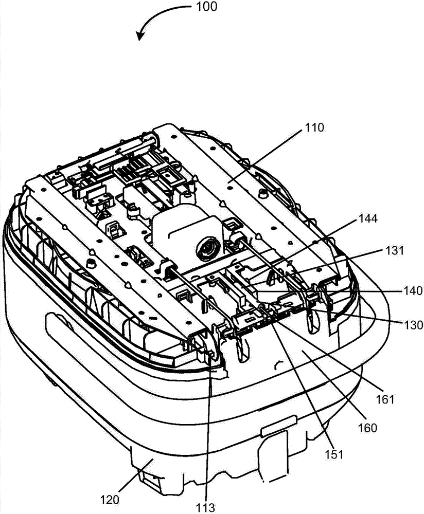
[0038] figure 1 Is a schematic view of a cooking appliance according to a preferred embodiment of the present invention, with the face of the lid removed for clarity. It can be understood that the cooking appliance according to the present invention can be an electric rice cooker, an electric pressure cooker or other cooking appliances, and the cooking appliance according to the present invention can also have various functions such as porridge cooking in addition to the function of cooking rice.

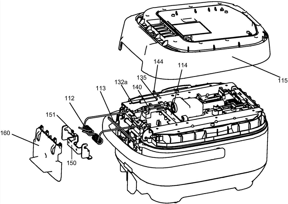
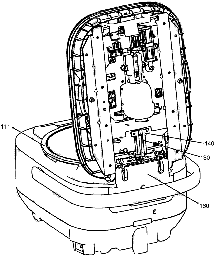
[0039] Such as Figure 1-Figure 3As shown, the cooking appliance 100 includes a lid body 110 and a pot body 120 . The pot body 120 is usually in the shape of a rectangular parallelepiped with rounded corners, and has a cylindrical concave cavity for accommodating the inner pot 111. The inner pot 111 can be freely put into or taken out from the concave cavity, so as to facilitate the adjustment of the inner pot. 111 for cleaning. The upper surface of the inner pot 111 has a circul...

Embodiment approach 2

[0053] Reference below Figure 11-Figure 13 A cooking appliance according to a second embodiment of the present invention is described, in which embodiment, the cooking appliance 200 has substantially the same structure as the cooking appliance 100 except for the structure of the stopper assembly. Thus, structures having substantially the same functions as those in the first embodiment will not be described in detail here for the sake of brevity.

[0054] Such as Figure 11-Figure 13 As shown, the limiting assembly includes a limiting seat 240 and a limiting cavity 241 formed in the limiting seat 240 . The limit seat 240 is assembled on the inner lining 214 of the cover body 210 , preferably, the limit seat 240 may be integrally formed with the inner liner 214 of the cover body 210 . The inside of the limiting seat 240 forms a limiting cavity 241 , the damper body 231 is connected in the limiting cavity 241 and can move in the limiting cavity 241 along a direction substantia...


PUM


Abstract

The invention discloses a cooking utensil. The cooking utensil comprises a cooker body, a cover body, a cover opening auxiliary component and a damper, wherein the cover body is pivotally connected with the cooker body, the cover body can cover the cooker body, so that a cooking space is formed between the cover body and the cooker body; the cover opening auxiliary component is connected to the cover body and applies an elastic acting force to the cover body so that the cover body can be elastically opened; the damper is arranged at the rear end of the cover body, and comprises a damper main body and a damping rod which can move relative to the damper main body, one end of the damper is connected to the cooker body, and the total length of the damper can be changed along with the rotation of the cover body. According to the cooking utensil disclosed by the invention, the smooth cover opening can be realized.

Description

technical field [0001] The present invention relates to cooking appliances. Background technique [0002] In the process of opening the lid of many cooking utensils currently on the market, the pot body will vibrate or become unstable due to the release of the elastic potential energy of the spring at the junction of the lid and the pot body, and noise will be generated simultaneously. Especially when there is no food in the pot, the shaking phenomenon is more serious. Moreover, the shaking of the pot body may cause friction and collision between the inner pot and the heating plate, damage the inner pot body and coating, and reduce the overall service life of the cooking utensil. In addition, when soup is contained in the pot, there is a hidden danger of scalding consumers after the soup splashes out. [0003] Therefore, there is a need to provide a cooking appliance that at least partially addresses the above mentioned problems. Contents of the invention [0004] A ser...

Claims


Application Information

Patent Timeline
Patent Type & Authority Applications(China)
IPC IPC(8): A47J36/12
CPCA47J36/12
Inventor 刘一琼钟辰根彭军王红林
Owner ZHEJIANG SUPOR ELECTRICAL APPLIANCES MFG CO LTD
Learn More